Page 6
Bolt Spec and Tightening Procedure
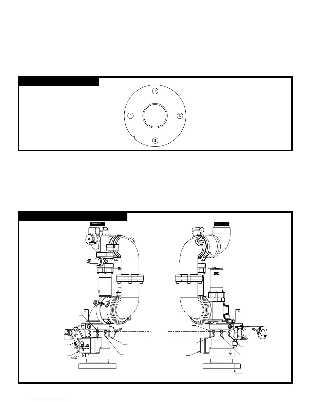
Use four 5/8” bolts and nuts of grade ve minimum and suitable washers. There must be a minimum of six threads of
engagement. Use a ring gasket conforming to ASME 16.21. The notch that is cut into the side of the inlet ange is the
front of the monitor (see Figure 2).
Start the bolt tightening procedure by lubricating the nuts and bolts. Hand tighten the nuts until they are snug against
the ange. The nal torque of the bolts should be a maximum of 100 lb-ft. Following the correct sequential order as
shown in gure 2, tighten the bolts to 30% of the nal torque. Repeat the tightening sequence to 60% of the nal
torque. Repeat a third time to 100% of the nal torque. Finally, repeat the sequence at the nal torque.
Rotational Hard Stops
The stainless steel rotational hard stops set the boundaries for the area that the monitor is allowed to travel left
(counterclockwise) and right (clockwise). The stop in the lower row controls the left (CWW) travel, and the stop in the upper
row controls the right (CW) travel. Refer to gure 3 for the locations of the upper row and the lower row, as well as points 1-5.
The monitor is shipped with a stop in the lower row at point 1, which stops the monitor at -170° CCW, and a stop in the
upper row at point 5, which stops the monitor at +170° CW. To set a different boundary area, swap the positions of the
steel hard stop and a plastic plug. Refer to gure 4 to select a desired boundary area. Both the stops and the plugs
have a 1/2” hex head.
FIGURE: 2 - Bolt Torque Order
FIGURE: 3 - Hard Stop and Plug Locations
HARNESS
JUNCTION BOX
#2
#3
NOTCH AT
FRONT OF
MONITOR
#4
#5
UPPER ROW
LOWER ROW
HARNESS
#1
#2
#3
#4