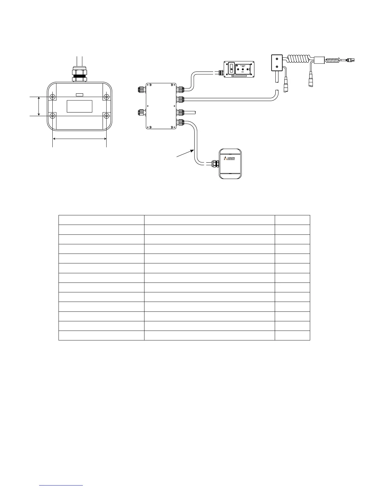
MECHANICAL ATTACHMENT OF RECEIVER
Belowarethemountingholedimensionsforthereceiver.Mountthereceivertoallowenoughcableforproper
installationtotheLogicBox(SeeElectricalLayout).Thereceiverwillcomewitha10ft.cable.
ELECTRICAL INSTALLATION OF RECEIVER
The following is the wiring chart for the Receiver to the Logic Box. These color-coded wires should be wired into the
inputsideoftheLogicBox(TB1).The+V(power)and-V(ground)canbewiredintoTB2.
*TheAuxbuttoncanbeusedforStow,DeployorOscillationifavailableonthemonitor.Wirethewhite/redwireintothe
correspondingterminalrequestedbycustomerfortheappropriatefunction.Seemonitoroperatinginstructions(orLogic
BoxLid)forwiringdiagramandterminallocation.**RunjumperwirefromTB3#7toTB3#3tohavetheAuxLEDonthe
handheld controller indicate if the monitor is stowed or deployed.
•AuxLEDON-Deployed
•AuxLEDOFF-Stowed
SYNCHRONIZE HANDHELD CONTROLLER WITH RECEIVER
•Beforeinitialoperationcanoccur,theHandheldControllermustbesynchronizedwiththeReceiver.
This allows proper communication between the two and ensures that the handheld Controller will only
controltheoperationofoneReceiver.Synchronizationisperformedonlyoncewhenthesystemisput
intooperationforthersttimeorifitbecomesdesirabletosynchronizetheHandheldControllerwitha
differentReceiver.AnunsynchronizedHandheldwillashallLED’sinunisonwhenitisturnedon.This
willcontinueforapproximately20secondsatwhichtimetheunitwillpowerdown.NewHandheld
controllersareshippedunsynchronized.
RECEIVER WIRE COLORS TERMINAL POSITION IN LOGIC BOX
WHITE +V12/24VPOWER TB1#10
WHITE/BLACK -VGROUND TB3#15
GRAY LED TB3#8**
WHITE/RED AUX *
BLACK RIGHT TB1#6
RED LEFT TB1#5
BLUE DOWN TB1#4
GREEN UP TB1#3
YELLOW STREAM TB1#2
BROWN FOG TB1#1
ORANGE STOW(USEDONLYFORSIT) TB1#21
PURPLE DEPLOY(USEDONLYFORSIT) TB1#22
FOGLEFTLOWER
RAISERIGHT
STOW
DEPLOY
SS
WARNING
FOGLEFTLOWER
RAISERIGHT
STOW
DEPLOY
SS
WARNING
1.33"
3.89"
10ft.
Cable
Logic
Box
Receiver
ELECTRICAL LAYOUT
2
 Loading...