Do you have a question about the Albrecht AE 497 W and is the answer not in the manual?
Technical details including frequency range, stability, tolerance, emission modes, microphone, and physical characteristics.
Details on power output, spurious emissions, current drain, and modulation frequency response.
Key receiver parameters such as sensitivity, selectivity, image rejection, and audio output.
Controls the transceiver's power status.
Socket for connecting mono headphones with specific impedance requirements.
6-pin socket for connecting a standard electret hand microphone.
Adjusts the audio output level.
Mutes receiver noise when no signal is present; sensitivity is adjustable.
Fine-tunes transmit output power.
Adjusts frequency for optimizing AM and SSB reception/transmission.
Controls receiver sensitivity and microphone modulation.
Rotary switch for selecting operating frequency steps.
Calibrates the meter for accurate standing wave ratio reference.
Switch to select meter scale for Modulation, Calibration, or SWR.
Selects operation mode (AM/FM/USB/LSB) or controls memory functions.
Manages saving or loading channels into memory.
Recalls last channel or manages memory channel 4.
Accesses reprogrammed frequencies (memory 2) or manages memory.
Adjusts instrument and keyboard illumination brightness.
Activates secondary functions of double-function switches.
Selects frequency steps or activates Noise Blanker.
Controls scan mode, shift direction for repeaters, or memory.
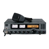
Shows frequency, channels, and operational status.
Displays SWR calibration and modulation levels during transmission.
Indicates incoming signal strength (receive) or RF power (transmit).
Displays relative incoming signal strength and RF output power.
Explains how to use the meter for modulation and SWR readings.
Step-by-step guide to calibrate the SWR meter.
Factors to consider when choosing a location for the radio unit.
Guidance on selecting and matching antennas for optimal transmission.
Steps for turning on the radio and adjusting for optimal reception.
Steps for selecting frequency, speaking into the microphone, and transmitting.
Explanation of SSB signal reception and mode selection.
Compares SSB and AM reception, highlighting benefits of SSB.
Details how USB and LSB modes affect frequency and intelligibility.
Explains how the Clarifier control fine-tunes SSB signals.
Pinout and wiring notes for the 6-pin microphone socket.
Details on connecting external speakers and headphones.
Information on special channel configuration modes for service personnel.
Contact details for repair and warranty matters in Germany and abroad.
Steps to activate channelized mode via FUNC and 2/Call.
Provides a frequency table for the activated channel mode.
Declares compliance with EU directives and harmonized European standards.
Specifies authorized users and the purpose of amateur radio service.
Details of Alan Electronics GmbH and contact person for the declaration.
| Brand | Albrecht |
|---|---|
| Model | AE 497 W |
| Category | Accessories |
| Language | English |