LEDs and Optics
7450 ESS-7 Page 111
SF/CPM LEDS
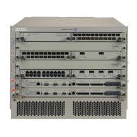
Figure 37 displays the SF/CPM front panel faceplate.
Figure 37: SF/CPM Front Panel
Table 36 describes the fields and LED states.
2 24 9 10
13
1 15 6 7 8 11 123
ESS1004
Table 36: SF/CPM Field Descriptions
Key Label/Part Sub
category
Description
1 Captive screws Secures the SF/CPM in place.
2 Ejector lever Ejector levers are used to seat and disengage the connectors to and from
the backplane.
3 Reset A recessed button used to restart the SF/CPM. Insert a small object such
as a pen tip to depress the button.
Power • Blue: Power on.
• Unlit: Power off.
Status • Green: Operationally up and administratively up.
• Amber: Operationally down but administratively up.
• Amber (blinking): Qualified, but previously failed.
• Unlit: Not operational, shutdown, or administratively down.
M/S Ctl Master/Slave SF/CPM designation:
• Green: Indicates that the SF/CPM is designated as the primary SF/CPM
in a redundant system.
• Green (blinking): Indicates that the SF/CPM is operating as the
secondary SF/CPM in a redundant configuration.
 Loading...
