Chassis Features
Page 16 7450 ESS-7
CHASSIS FEATURES
In the 7450 ESS-7 chassis, the top slots, numbered 1 through 5, are reserved for input/output
module (IOMs) cards. The module slots are horizontally oriented. A maximum of two MDAs can
be installed on each IOM. MDAs are installed in either MDA slot 1 (left slot) or MDA slot 2 (right
slot) on an IOM.
The 2 bottom module slots, labeled A and B, are reserved for the SF/CPM cards. At least one SF/
CPM must be installed in order for the system to operate. The redundant SF/CPM operates in
standby mode and takes over system operation if the primary fails.
The Alcatel-Lucent 7450 ESS-7 chassis provides access to components from both the front and
back. The SF/CPM, IOMs, MDAs, and AC-to-DC power converter can be accessed from the front
of the chassis. The AC and DC PEMs, fan and filter trays are accessible from the chassis rear.
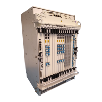
Figure 1 shows a front view of the 7450 ESS-7 chassis with AC PSMs installed in the lower front
power bays. The mounting brackets for the 7450 ESS-7 chassis are factory installed to front mount
the chassis in a standard 19-inch wide rack. Refer to Table 2 for key descriptions. Figure 2 displays
the front view with the front safety cover installed.
Figure 1: 7450 ESS-7 Chassis Front View (with AC-Power Converters)
6
7
8
1
2
3
5
4
ESS7002

 Loading...