EasyManua.ls Logo

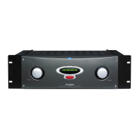
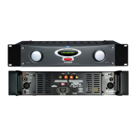
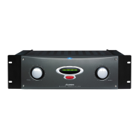
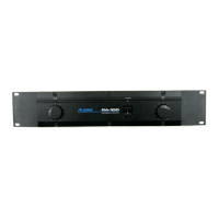
Alesis Matica 500 User Manual

Alesis Matica 500
22 pages
To Next Page IconTo Next Page
Page #1 background imageLoading...
Page #1 background image
ALESIS
MATICA 500/900
(A4/A8)
Service Manual
P/N: 8-31-0030-A

Other manuals for Alesis Matica 500

Questions and Answers:

Alesis Matica 500 Specifications

General IconGeneral
TypePower Amplifier
Channels2
Input Impedance20 kOhms balanced, 10 kOhms unbalanced
S/N Ratio>100 dB
THD<0.03%
InputsXLR and 1/4" TRS
OutputsBinding posts
Frequency Response20Hz - 20kHz
CoolingConvection
Dimensions19" x 3.5" x 15.75" (483 x 89 x 400 mm)
Weight35 lbs (15.9 kg)

Summary

1.00 Theory of Operation

1.10 Input Section

The input stage uses a dual Signetics 5532A op amp for a low noise, balanced to unbalanced converter with a maximum input level of +21dBm.

1.20 Pre-Amp Section

The pre-amp section uses Signetics 5532A op amps for push-pull characteristics, providing 15.7 dB gain per channel, with channel A inverting and B non-inverting.

1.30 Main Amplifier Section

The main amplifier is inverting, composed of front end, voltage gain stage, output driver, and output stage, with a closed-loop gain of 10X or 20dB.

1.40 Output Device Protection

Output device protection uses Q17 (NPN) and Q18 (PNP) complimentary circuits to prevent damage from short circuits or DC offset.

1.50 Bias Circuit

The bias circuit is an active shunt regulator, providing lower impedance and better control of bias voltage compared to single-device regulators.

1.60 Speaker Protection

Speaker protection has two sections: a quad comparator with low-pass filter and a discrete bipolar transistor circuit controlling speaker relays.

1.70 Fan Speed Control

The fan circuit has three modes: elevated speed at power-up, slow speed, and speed modulated by amplifier drive or heat sink temperature.

1.80 Thermal Management System

The extruded aluminum heat sink with forced air cooling manages heat dissipation, with fan speed controlled by amplifier demands and heat sink temperature.

2.00 Updates and Corrections

2.10 Stripped Heat Sinks

Procedure for reusing stripped heat sinks using a machine screw and threaded standoff to maintain clamp pressure.

2.20 New Case Bracket Insulator(s)

Replacement of insulators to prevent wire insulation from being cut by case brackets, protecting the user from electric shock.

2.30 Transformer Insulators

Foam insulators added for electrical isolation and resistance to mechanical shock, placed on the case top over transformers.

3.00 Troubleshooting

4.00 A4 Service Parts List

4.10 A8 Service Parts List

Related product manuals