EasyManua.ls Logo

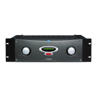
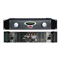
Alesis Matica 900 User Manual

Alesis Matica 900
22 pages
To Next Page IconTo Next Page
Page #1 background imageLoading...
Page #1 background image
ALESIS
MATICA 500/900
(A4/A8)
Service Manual
P/N: 8-31-0030-A

Other manuals for Alesis Matica 900

Questions and Answers:

Alesis Matica 900 Specifications

General IconGeneral
TypePower Amplifier
Channels2
S/N Ratio> 100 dB
Input ConnectorsXLR, 1/4" TRS
Dimensions19" x 3.5" x 15.5"
Power Output900 W (bridged 8 Ohms)
Frequency Response20 Hz - 20 kHz, +0, -0.5 dB
THD< 0.03%
Input Impedance20k Ohms
Output ConnectorsBinding Post
CoolingVariable speed fan

Summary

Theory of Operation

Input Section

The input stage is made up of a dual Signetics 5532A op amp. This is a low noise selected version of the 5532.

Pre-Amp Section

The pre-amp section also uses the Signetics 5532A op amp. The circuits of the pre-amp are of opposing signal polarity.

Main Amplifier Section

The main amplifier is composed of four sections: The monolithic front end. A complimentary voltage gain stage or transconductance stage.

Output Device Protection

Output device protection is accomplished with a relatively simple circuit. The protection circuit is broken up into Q17 that protects the NPN output devices and Q18 that protects the PNP output devices.

Bias Circuit

The bias circuit is more that just a single device Vbe multiplier seen in many audio amplifiers. The circuit consists of an active shunt regulator.

Speaker Protection

There are two sections to the speaker protection circuit. A section made up of a quad comparator with a low pass filter before it and a discrete bipolar transistor circuit.

Fan Speed Control

The fan circuit has three modes of operation in which it varies the speed of the fan depending on demand or condition.

Thermal Management System

The large extruded aluminum heat sink in the center of the chassis is the heart of the amplifiers heat dissipation scheme. It is a forced air cooling system.

Updates and Corrections

Stripped Heat Sinks

Occasionally when tightening down the heat sink clamps one of the screws will strip the threads out of the heat sink itself.

New Case Bracket Insulator(s)

It was found that it was possible for the insulation on the wires from the main power transformer(s) could over time be cut by the case bracket(s).

Transformer Insulators

These foam insulators were added for two purposes: Electrical Isolation, Added resistance to mechanical shock.

Troubleshooting

Related product manuals