ELECTRONIC CONTROL BOX
O
R
I
G
I
N
A
L
01.20
ESD 1099 -4-
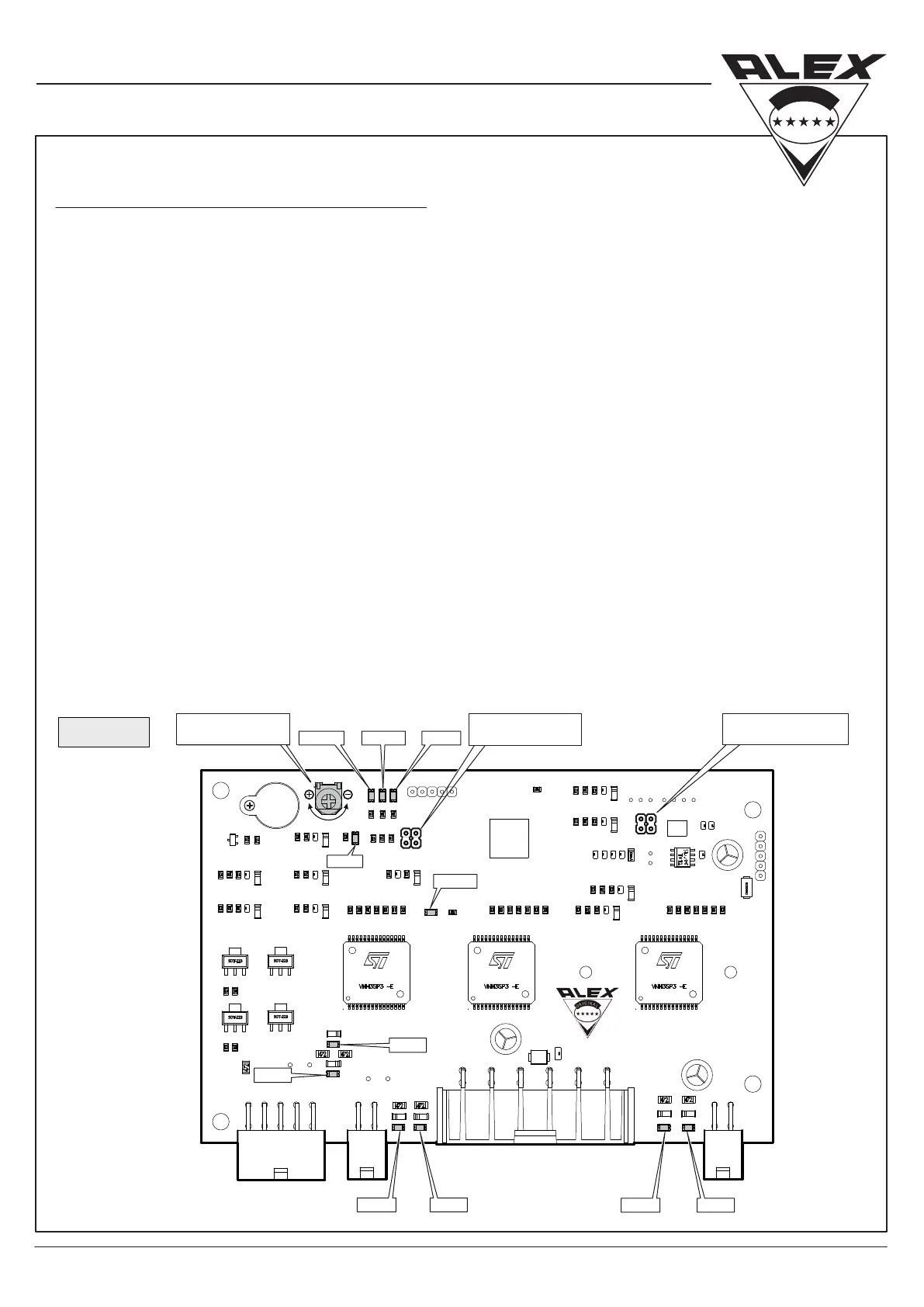
PCB leds color and number for all functions.
LED1 (White) – Remote Control-1
LED3 (White) – Motor A Opening
LED4 (Red) – Motor A Closing
LED5 (White) – Motor B Opening
LED6 (Red) – Motor B Closing
LED7 (White) – Actuator Opening
LED 5 LED 6
LED 3 LED 4
LED 13
LED 7
LED 8
LED 1
Potentiometer adjustment for intensity level of stopping door while closing
To reduce sensitivity of Electric Door turn the Potentiometer clockwise (-).
To Increase sensitivity turn the Potentiometer counter clockwise (+).
Reprogramming sliding door Electronic Control Box:
(In case or belt replacement)
1. Turn o ignition key.
2. Disconnect the black connector.
3. Reconnect the black connector.
4. Turn on ignition key.
5. Press and hold driver switch for 10 seconds Within time window of 30 seconds.
6. The door will operate by itself – when the door stops in open position, it is ready for use.
LED 12 LED 9LED 11
LED8 (Red) – Actuator Closing
LED9 (Red) – Door Opened Led
LED11 (Yellow) – Ignition
LED12 (Blue) – Driver Command
LED13 (Blue) – Remote Control-2
*
Adjustment will take aect after turning ignition key o and on.
SENSITIVITY
POTENTIOMETER
DOOR POSITION
PROGRAMING
REMOTE CONTROL
PROGRAMING
(g. C)
 Loading...