14
Power and Signal Connections
Power can be supplied to your controller through either the power jack or the
multi-pin connector on top of your device.
Small valve controller power jacks require a 12-30 Vdc power supply
with a 2.1 mm female positive center plug capable of supplying at
least 250 mA. 4-20 mA analog signal outputs require at least 15 Vdc, ,
and 0-10 Vdc outputs require at least 10 Vdc..
Large valve controllers require a 24-30 Vdc power supply with a 2.1
mm female positive center plug capable of supplying at least 750 mA.
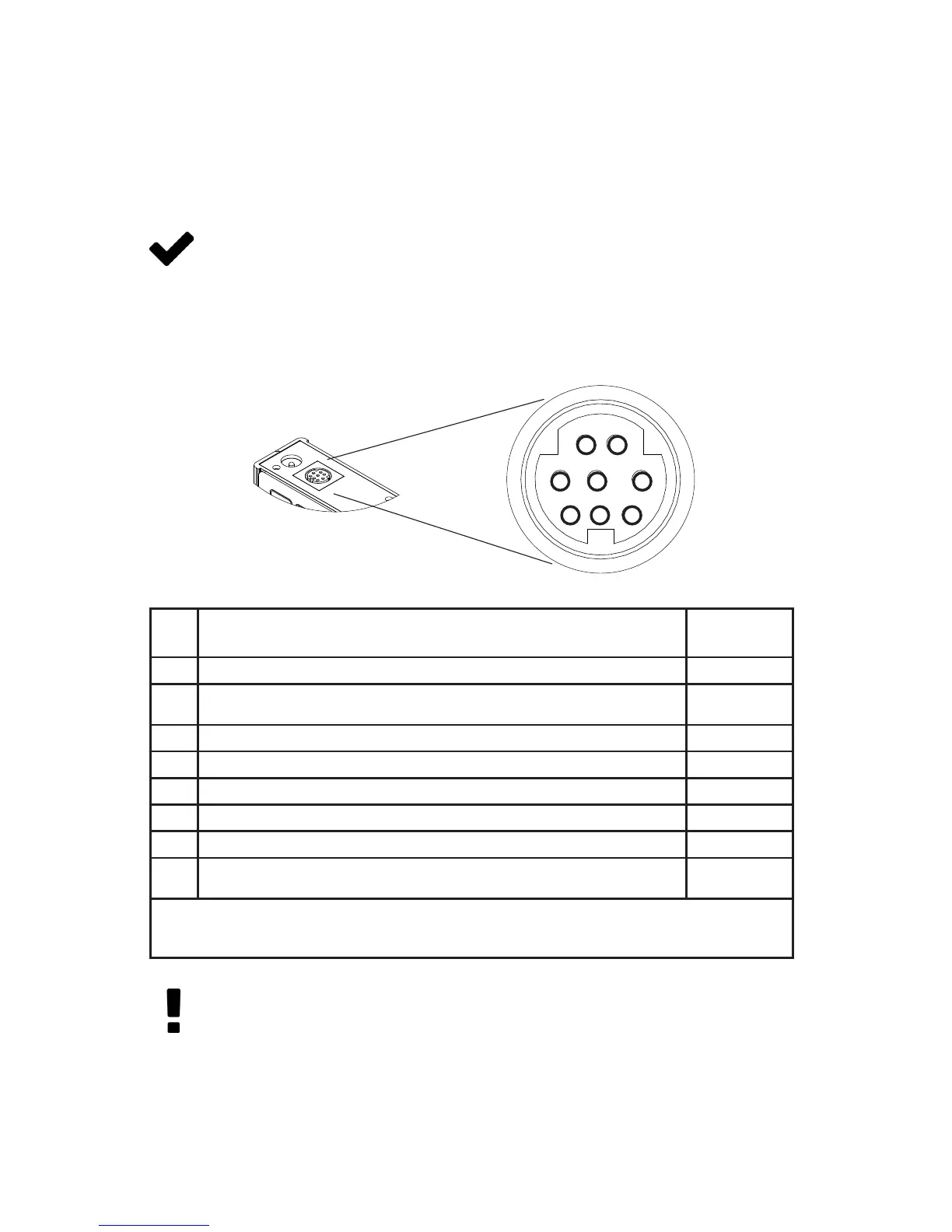
Standard 8-Pin Mini-DIN Pinout
Pin Function
Mini-DIN
cable color
1
Not Connected (or optional 4-20 mA Primary Output Signal)
Black
2
Static 5.12 Vdc (or optional Secondary Analog Output [4-20 mA, 0-5 Vdc,
1-5V dc, 0-10 Vdc] or Basic Alarm)
Brown
3
Serial RS-232RX / RS-485(–) Input Signal (receive) Red
4
Analog Setpoint Input Orange
5
Serial RS-232TX / RS-485(+) Output Signal (send) Yellow
6
0-5 Vdc (or optional 1-5 Vdc or 0-10 Vdc) Output Signal Green
7
Power In (as described above) Blue
8
Ground (common for power, digital communications, analog signals and
alarms)
Purple
Note: The above pinout is applicable to all the ow controllers and controllers with the Mini-DIN
connector. The availability of dierent output signals depends on the options ordered. Optional
congurations are noted on the unit’s calibration sheet.
1 2
3 4 5
6 7 8
Getting Started
Caution: Do not connect power to pins 1 through 6, as permanent
damage can occur.
It is common to mistake Pin 2 (labeled 5.12 Vdc Output) as the
standard 0-5 Vdc analog output signal. Pin 2 is normally a constant
5.12 Vdc that reects the system bus voltage.
For 6-pin locking industrial connector, DB9 and DB15 pinouts, see
page 92 to page 95 or visit alicat.com/pinout.
 Loading...