3141
THRU
3144
SENSITIVE
HALL-EFFECT SWITCHES
FOR HIGH-TEMP. OPERATION
115 Northeast Cutoff, Box 15036
Worcester, Massachusetts 01615-0036 (508) 853-5000
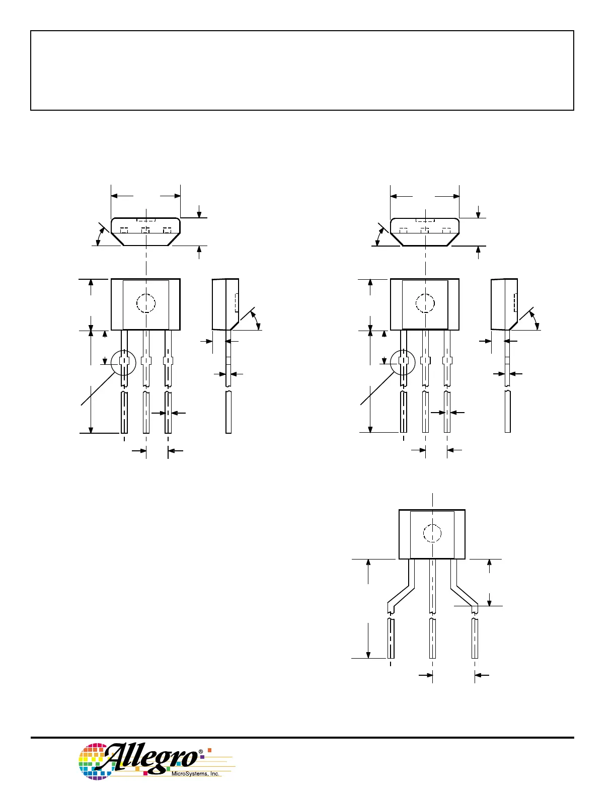
Dimensions in Inches
(controlling dimensions)
Dimensions in Millimeters
(for reference only)
PACKAGE DESIGNATOR ‘UA’
NOTES: 1. Tolerances on package height and width represent
allowable mold offsets. Dimensions given are
measured at the widest point (parting line).
2. Exact body and lead configuration at vendor’s option
within limits shown.
3. Height does not include mold gate flash.
4. Recommended minimum PWB hole diameter to clear
transition area is 0.035" (0.89 mm).
5. Where no tolerance is specified, dimension is nominal.
6. Supplied in bulk pack (500 pieces per bag).
Dwg. MH-014E in
0.164
0.159
0.062
0.058
0.0173
0.0138
0.050
BSC
45°
0.640
0.600
0.0189
0.0142
0.085
MAX
45°
0.031
123
0.122
0.117
SEE NOTE
Dwg. MH-014E mm
4.17
4.04
1.57
1.47
0.44
0.35
1.27
BSC
45°
16.26
15.24
0.48
0.36
2.16
MAX
45°
0.79
123
3.10
2.97
SEE NOTE
Radial Lead Form (order A314xxUA-LC)
NOTE: Lead-form dimensions are the nominals produced on the
forming equipment. No dimensional tolerance is implied or
guaranteed for bulk packaging (500 pieces per bag).
0.620"
0.500"
(15.7 mm
12.7 mm)
0.100"
(2.5 mm)
Dwg. MH-026
0.108"
(2.74 mm)
123
 Loading...