Publication 2092-UM001D-EN-P — July 2005
Installing Your Ultra1500 1-17
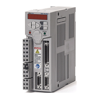
Figure 1.6
Ultra1500 Mounting Diagrams and Measurements
Dimensions are in millimeters (inches). Drives are designed to metric dimensions; inches are a mathematical conversion.
5.0
(0.20)
5.0
(0.20)
Mounting hole (top)
and slot (bottom)
require M4 x 10 bolts
Chassis ground
terminal
12.0
(0.47)
140.0
(5.51)
153.0
(6.02)
55.0
(2.17)
155.0
(6.10)
2092-DA1 and 2092-DA2
50.0
(1.97)
20.0
(0.79)
5.0
(0.20)
5.0
(0.20)
145.0
(5.70)
Mounting hole (top) and
slot (bottom) require
M4 x 10 bolts
Chassis ground terminals (2)
12.0
(0.47)
140.0
(5.52)
153.0
(6.02)
55.0
(2.17)
155.0
(6.10)
70.0
(2.76)
2092-DA3
63.0
(2.48)
27.0
(1.06)
5.0
(0.20)
5.0
(0.20)
Mounting hole (top) and slot
(bottom) require M5 x 10 bolts
Chassis ground
terminals (2)
12.0
(0.47)
185.0
(7.28)
198.0
(7.80)
55.0
(2.17)
155.0
(6.10)
90.0
(3.54)
2092-DA4 and 2092-DA5
50.0
(1.97)
5.0
(0.20)
145.0
(5.70)
145
(5.70)
 Loading...