Publication 2092-UM001D-EN-P — July 2005
2-2 Ultra1500 Connector Data
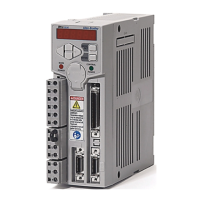
Ultra1500 Front Panel Connections
Use the figure below to locate the front panel connections on the Ultra1500
drives.
Figure 2.1
Ultra1500 Front Panel Connections
Note: Ultra1500 Operator Interface controls are described in Appendix D.
UVW
P1P2B1B2
L1L2L2CDC-
L3
L1C
CN3
CN2
BATT
CN1
7-Segment LED Display
Left/Right and
Up/Down Keys
Main Power Indicator
Enter Key
Control Power Indicator
CN2 – Motor Feedback
CN1 – Input/Output
Input Power
DC Bus and Shunt Power
Motor Power
Battery Holder
CN3 – Serial Interface
Mode/Set Key
50-pin CN1
I/O Connector
20-pin CN2 and CN3
Motor Feedback and
Serial Connectors
Pin 20
Pin 1
Pin 10
Pin 11
Pin 50
Pin 1
Pin 25
Pin 26
ATTENTION
The N terminal (labelled DC- on the removable connector) IS NOT an
Input Power connection.
 Loading...