EasyManua.ls Logo

Allied Air 4SHP13 series User Manual

Allied Air 4SHP13 series
26 pages
To Next Page IconTo Next Page
Page #1 background imageLoading...
Page #1 background image
506272-01 Page 1 of 26Issue 0921
The equipment covered in this manual is to be installed by trained and experienced
service and installation technicians. Improper installation, modification, service, or
use can cause electrical shock, fire, explosion, or other conditions which may cause
personal injury, death, or property damage. Use appropriate safety gear including
safety glasses and gloves when installing this equipment.
WARNING
Risk of electrical shock. Disconnect all remote power
supplies before installing or servicing any portion of the
system. Failure to disconnect power supplies can result
in property damage, personal injury, or death.
WARNING
Installation and servicing of air conditioning equipment
can be hazardous due to internal refrigerant pressure
and live electrical components. Only trained and
qualified service personnel should install or service
this equipment. Installation and service performed by
unqualified persons can result in property damage,
personal injury, or death.
WARNING
Sharp metal edges can cause injury. When installing
the unit, use care to avoid sharp edges.
WARNING
TABLE OF CONTENTS
INSTALLATION ....................................................2
START-UP ..........................................................12
OPERATION ......................................................17
MAINTENANCE .................................................18
HOMEOWNER INFORMATION .........................19
WIRING DIAGRAM ............................................22
WARRANTY.......................................................26
Manufactured By
Allied Air Enterprises Inc.
A Lennox International Inc. Company
215 Metropolitan Drive
West Columbia, SC 29170
*506272-01*
Save these instructions for future reference
INSTALLATION AND MAINTENANCE INSTRUCTIONS
4SHP13 Series
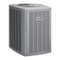
Split System Heat Pump

Other manuals for Allied Air 4SHP13 series

Question and Answer IconNeed help?

Do you have a question about the Allied Air 4SHP13 series and is the answer not in the manual?

Allied Air 4SHP13 series Specifications

General IconGeneral
Series4SHP13
SEERUp to 13
HSPFUp to 7.7
RefrigerantR-410A
SEER RatingUp to 13
HSPF RatingUp to 7.7
Voltage208/230V
Phase1
StagesSingle Stage
Cooling Capacity18000 - 60000 BTU/h

Summary

INSTALLATION

Electrical and Refrigerant Connections

Procedures for electrical wiring and refrigerant piping.

Refrigerant Line Installation

Line Set Isolation Techniques

Methods for isolating refrigerant lines to reduce vibration transmission.

Refrigerant System Preparation

Brazing Procedure

Step-by-step guide for brazing refrigerant line connections.

Flushing Contaminated Systems

Procedure for flushing contaminated refrigerant lines and coils.

System Flushing and Metering Devices

Flushing Procedures

Detailed steps for flushing the refrigerant system and lines.

Metering Device Installation

Service Valve and Leak Testing

Service Valve Operation

Procedures for operating liquid and suction line service valves.

Leak Detection Methods

Methods for checking the system for refrigerant leaks.

System Leak Testing and Evacuation

Evacuation Procedures

Critical steps for evacuating the system to remove noncondensables.

START-UP PROCEDURES

Unit Start-Up Steps

Procedures for starting up the unit after installation.

Refrigerant Charging and Adjustment

Guidelines for charging the system with R-410A refrigerant and adjustments.

Charging Methods

Weigh-In and Subcooling Charging

Methods for charging the system by weight or subcooling.

Refrigerant Charging Data

Subcooling and Superheat Calculations

Tables for determining subcooling and superheat values for system charging.

OPERATION OVERVIEW

MAINTENANCE AND DIAGNOSTICS

Routine Maintenance Checks

Routine checks and maintenance procedures for the system.

Start-Up and Performance Checklist

Wiring Diagram (Figure 14)

Wiring Diagram (Figure 15)

Wiring Diagram (Figure 16)

LIMITED WARRANTY INFORMATION

EXTENDED LIMITED PARTS WARRANTY

Related product manuals