AT-8124XL Installation Guide
7
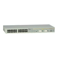
Figure 4 illustrates a network that consists of several AT-8124XL switches
that have been interconnected to form a large network. Port 24 on each
AT-8124XL switch has been configure as MDI and has been connected without
a crossover cable to a port on another switch. Port 24 on Switch #3 has been
connected to an Ethernet hub.
Figure 4 Multiple Switch and Hub Network Topology
10BASE-T / 100BASE-TX
FAST ETHERNET SWITCH
10BASE-T / 100 BASE -TX
FAST ETHERNET SWITCH
10BASE-T / 100BASE-TX
FAST ETHERNET SWITCH
10BASE-T/100BASE-TX NETWORK PORTS
POWER
4X5X6X7X8X9X 12X3X
AT-8124XL Switch #1
AT-8124XL Switch #2
AT-8124XL Switch #3
Ethernet Hub
 Loading...