AT-9000 Switch Command Line User’s Guide
651
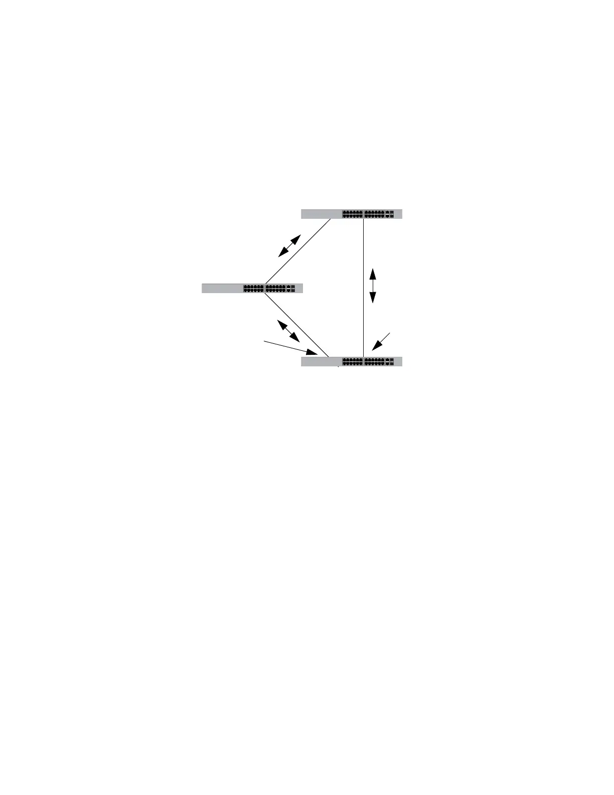
In the first example, the root bridge stops transmitting BPDUs. If switch 3 is
not using loop guard, it continues to forward traffic on port 4. But since no
BPDUs are received on the port, it assumes that the device connected to
the port is not an RSTP device. Since switch 2 becomes the new root
bridge, port 14 on switch 3 transitions to the forwarding state from the
blocking state to become the new root port for the switch. The result is a
network loop.
Figure 123. Loop Guard Example 4
But if loop guard is active on port 4 on switch 3, the port is placed in the
blocking state since the reception of BPDUs is interrupted. This blocks the
loop. The port remains in the blocking state until it again receives BPDUs
or the switch is reset.
Switch 3
Switch 1
Old root bridge
Stops transmitting BPDUs
Port 4
Remains in the forwarding
state
Switch 2
New root bridge
Port 14
Transitions from the blocking state
to the forwarding state
 Loading...


