AT-FS750/24-41 Web User Interface Manual
2-1
Chapter 2
Product Introduction
Product Introduction
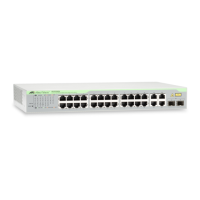
AT-FS750/24-41 is a L2 managed switch with 24-Port 10/100Mpbs ports , 2
10/100/1000Mbps ports and 2 Combo 10/100/1000Mbps/SFP ports. See below
for the introduction of switch outlook.
Providing a out-of-band connection to the Switch for management traffic.
By pressing the Reset button the Switch will change back to the default
configuration and all changes will be lost.
The Power LED lights up when the Switch is connected to a power source.
The Status LED lights up when the Switch works normally, and blinking indicates
the Switch is performing a system self-test
Port
Link/Act/Speed
LED (1-24)
The Link/Act/Speed LED flashes which indicates a network link through the
corresponding port. Blinking indicates that the Switch is either sending or
receiving data to the port. When a port has amber light indicates that port is
running on 10M. When it has a green light it is running on 100M.
Port
Link/Act/Speed
LED (25F, 26F, 25T,
26T, 27, 28)
The Link/Act/Speed LED flashes which indicates a network link through the
corresponding port. Blinking indicates that the Switch is either sending or
receiving data to the port. When a port has amber light indicates that port is
running on 10M or 100M. When it has a green light it is running on 1000M.
10/100M auto MDI/MDIX ports providing a FE connection for the Switch.
10/100/1000M Port
(25T, 26T, 27, 28)
10/100/1000M auto MDI/MDIX ports providing a GE connection for the Switch.
Installing the MiniGBIC module providing Gigabit fiber connection for the Switch.
MiniGBIC ports are shared with normal RJ-45 ports 25 and 26. When MiniGBIC
port is used, the RJ-45 port cannot be used.

 Loading...