Do you have a question about the Alnor AirGard 335 and is the answer not in the manual?
Details how to contact Alnor for service and support for any malfunctions.
Explains how the AirGard 335 monitors fume hood face velocity using airflow measurement.
Describes the bargraph, colored zones, and LEDs indicating airflow velocity changes.
Describes the continuous audible alarm for dangerous situations and relay output for remote notification.
Emphasizes that the monitor must be calibrated in the field on the specific fume hood it is installed on.
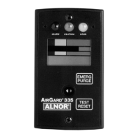
Identifies and labels the main components visible on the front of the AirGard 335 monitor.
Explains the meaning of Red (Alarm), Yellow (Caution), and Green (Good) status LEDs.
Describes the function of the Up, Down, Test/Reset, and Emergency Purge buttons.
Explains the Analog Bargraph, Colored Bands, and Digital Display functions.
Identifies the Air Inlet and Mounting Screws for the monitor.
Lists the tools needed for installing the AirGard 335 monitor.
Provides instructions on how to physically mount the monitor onto the fume hood.
Details the power jack and terminal block connections for wiring the monitor.
Explains how power is supplied to the monitor via the power jack.
Describes the terminal block for input/output features and wire gauge acceptance.
Explains the DIS INPUT function for remote Test/Reset, Emergency Purge, or Night Setback.
Explains the ALRM INPUT for remote activation of Test/Reset or Emergency Purge.
Identifies the common ground for DIS INPUT and ALRM INPUT connections.
Describes the function and contact states of Relay 1 and Relay 2.
Provides a diagram illustrating the field connections for the monitor.
Explains the importance and frequency of calibration for accurate readings.
Warns that calibration/configuration must be done by qualified personnel aware of hazards.
Lists the necessary tools for performing calibration.
Outlines the step-by-step process for calibrating the monitor.
Describes the display sequence during calibration initialization.
Informs about potential calibration errors and where to find more information.
Lists and explains error codes that may appear during calibration.
Explains how to acknowledge and re-attempt calibration after an error.
Provides tips to resolve specific calibration error codes like ErL, ErH, Err, Er2.
Details the steps to set the low alarm setpoint for the monitor.
Describes the initial display and LED activation when the monitor is powered on.
Explains how the bargraph and LEDs indicate airflow conditions during normal operation.
Explains how to perform a monitor test to check display, LEDs, and alarm outputs.
Details when the horn activates, how it stays on, and conditions for disabling/re-enabling.
Explains how to temporarily silence the horn using the Test/Reset button.
Describes how to permanently disable the horn and how to re-enable it.
Explains how to view the current low and high alarm set points.
Details the procedure for modifying the low and high alarm set points.
Warns that changes are not saved if the Test/Reset button is held too long.
Describes the LED behavior indicating the status of low, high, and night setback alarms.
Explains how to disable the high alarm and the role of Configuration Parameter P11.
Describes the Emergency Purge button function and its relay activation.
Explains that configurable parameters are stored in nonvolatile memory.
Describes how to enter the Configuration mode using the Test/Reset button.
Reinforces that changes are not saved if the Test/Reset button is held too long.
Summarizes how to navigate and save changes within the configuration menu.
Table listing factory default settings for programmable parameters (CAL, P01-P12, dEF).
Refers to Section 3 for field calibration procedures.
Explains how to enable or disable the numeric airflow velocity reading on the display.
Allows selection between feet per minute (fpm) and meters per second (m/s) for display.
Sets the duration for which the horn is silenced after acknowledgment.
Sets the delay before transitioning from caution to alarm, preventing toggling.
Sets the delay before transitioning from alarm to caution, preventing toggling.
Defines the starting point of the low caution zone, determining when the yellow LED activates.
Configures switch settings for Remote Test/Reset, Emergency Purge, or Night Setback features.
Explains how Night Setback operates based on contact closure or opening.
Describes the monitor's state (disabled, horn off, LEDs off) when Night Setback is OFF.
Explains how P12 sets the low alarm setpoint during Night Setback mode.
Configures switch settings for Remote Test/Reset, Emergency Purge, and Sash Override/Alarm Input.
Explains the remote activation of the Test/Reset function via a contact closure.
Explains the remote activation of the Emergency Purge function via a contact closure.
Differentiates between sash override and external alarm inputs and their indications.
Describes the configuration options for Relay Output 1, including contact states.
Table detailing various relay functions, displayed settings, and contact states for Relay Output 1.
Describes the configuration options for Relay Output 2, including contact states.
Table detailing various relay functions, displayed settings, and contact states for Relay Output 2.
Enables or disables the high alarm relay output for specific applications.
Sets the night setback low alarm value or disables it by setting to "OFF".
Resets configurable parameters (P01-P11) to their factory default values.
Lists and explains error codes that may appear during calibration and their causes.
Table detailing common problems, their possible causes, and corrective actions.
Provides contact information and shipping address for requesting technical assistance or service.
Shows the locations and size of mounting holes required for installation.
Indicates the dimensions for the cutout area on the fume hood for mounting.
Describes the 3-digit, 7-segment LCD with status indicators and bargraph.
Explains user-selectable units (fpm/m/s) and the operational display range.
Defines the accuracy and resolution of airflow velocity measurements.
Details alarm ranges, configurable delays, and horn silence options.
Describes the LED indications for alarm, caution, and normal states, and the alarm sound level.
Covers alarm relay output, emergency purge, external alarm, and sash override inputs.
States calibration requirement and provides instrument dimensions and mounting cutout size.
Lists recommended temperature, humidity, and storage conditions for the monitor.
Specifies the voltage range and power supply details for the monitor.
| Accuracy | ±3% of reading ±0.1 m/s |
|---|---|
| Display | LCD |
| Air Velocity Range | 0.2 to 30 m/s |
| Resolution | 0.01 m/s |
| Temperature Range | 0 to 50°C |
| Measurement Range | 0.2 to 30 m/s |
| Operating Temperature | 0 to 50°C |
| Weight | 500 g |