12
4.6 FIT THE FLUE - Figs. 12, 13
1. The following procedure applies to both rear or side exit flue. The only difference being the lengths to which the ducts are cut.
Rear flue Outer air duct length = finished wall thickness + 135 mm.
Inner flue duct length = finished wall thickness + 172 mm.
Side flue Outer air duct length = finished wall thickness + the distance from the inside wall to the side of the boiler + 145 mm.
Inner flue duct length = finished wall thickness + the distance from the inside wall to the side of the boiler + 182 mm.
2. If the overall length of the inner duct is greater than 750 mm then a flue extension is required. To fit an extension refer to
the following section.
3. Withdraw the inner flue duct from the outer air duct.
4. Mark the outer air duct to match the length given above, measure from the end of the tube as shown in Figs. 12 and 13.
5. Mark the inner flue duct to match the length given above.
6. Cut both the inner and outer ducts to length.
Note: Do not cut the outer duct end with the two holes, these are for securing the terminal.
Ensure that all cuts are square and burr free.
7. Fit the flue terminal to the outer duct ensuring it is fully located and secure with the two screws provided.
8. Place the inner flue duct back into the outer duct.
Alpha CB24/28 - Installation
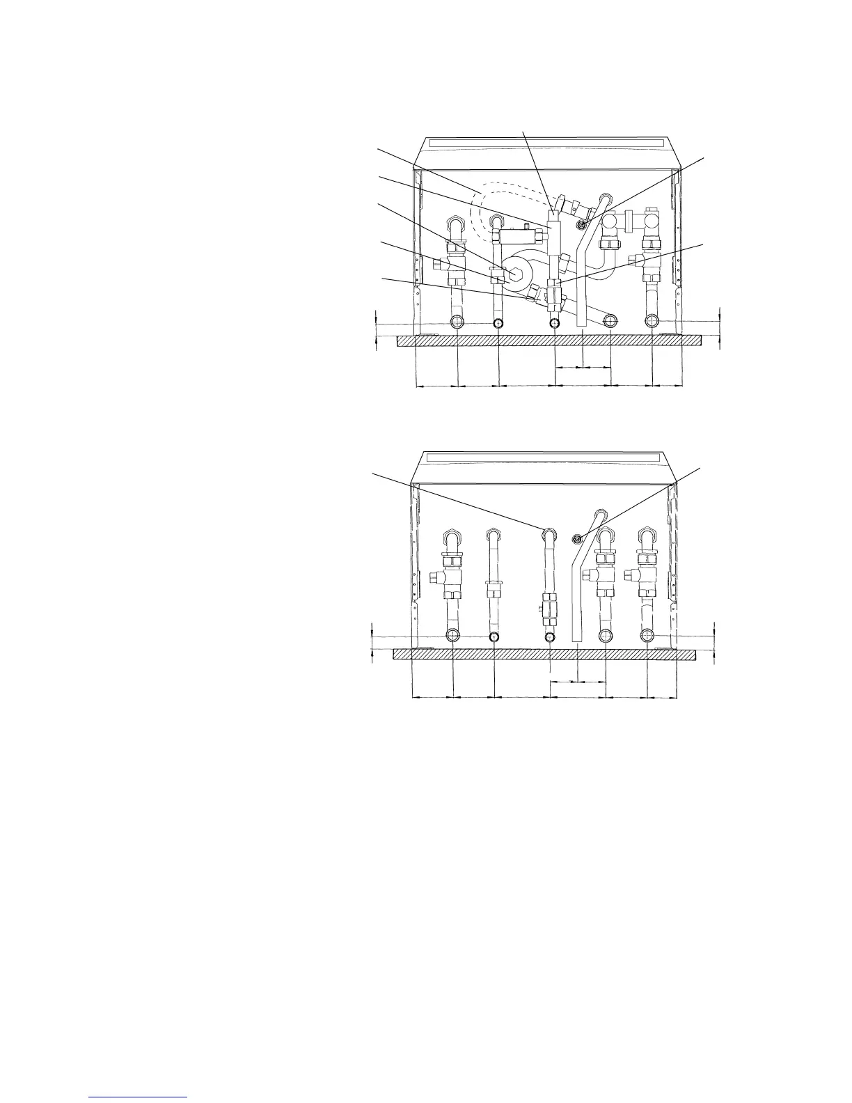
Fig. 11
A - Heating flow (22 mm)
B - Hot water outlet (15 mm)
C - Gas inlet (22 mm)
D - Cold water mains inlet (15 mm)
E - Heating return (22 mm)
F - Pressure relief valve (15 mm)
G- Heating drain point
H - Cold water inlet filter
I - Seasonality valve adjuster
J - Cyclone drain point
Note: Disconnect the filling loop after
filling the central heating system.
Alpha CB24 and CB28
Alpha CB24X
A - Heating flow (22 mm)
B - Hot water outlet (15 mm)
C - Gas inlet (22 mm)
D - Cold water mains inlet (15 mm)
E - Heating return (22 mm)
F - Pressure relief valve (15 mm)
G- Heating drain point
H - Cold water inlet filter
70 70 95 95 70 50
47.5 47.5
A
BCD
E
F
H
G
23
20
70 70 95 95 70 50
47.5 47.5
Filling loop
ABCDEF
H
G
23
20
J
I
Seasonality valve
Cyclone
Heating
return
valve