28
8.17 DHW FLOW SWITCH - Fig. 30
1. Gain access behind the front casing as described in Section 8.1.
2. Isolate the mains water supply and open all hot taps to drain any water from the boiler.
3. Disconnect the wires from the switch.
4. Undo the nuts at the inlet and outlet of the switch and undo the retaining nut at the bottom. Lift out the switch.
5. Fit the new switch and re-assemble in reverse order.
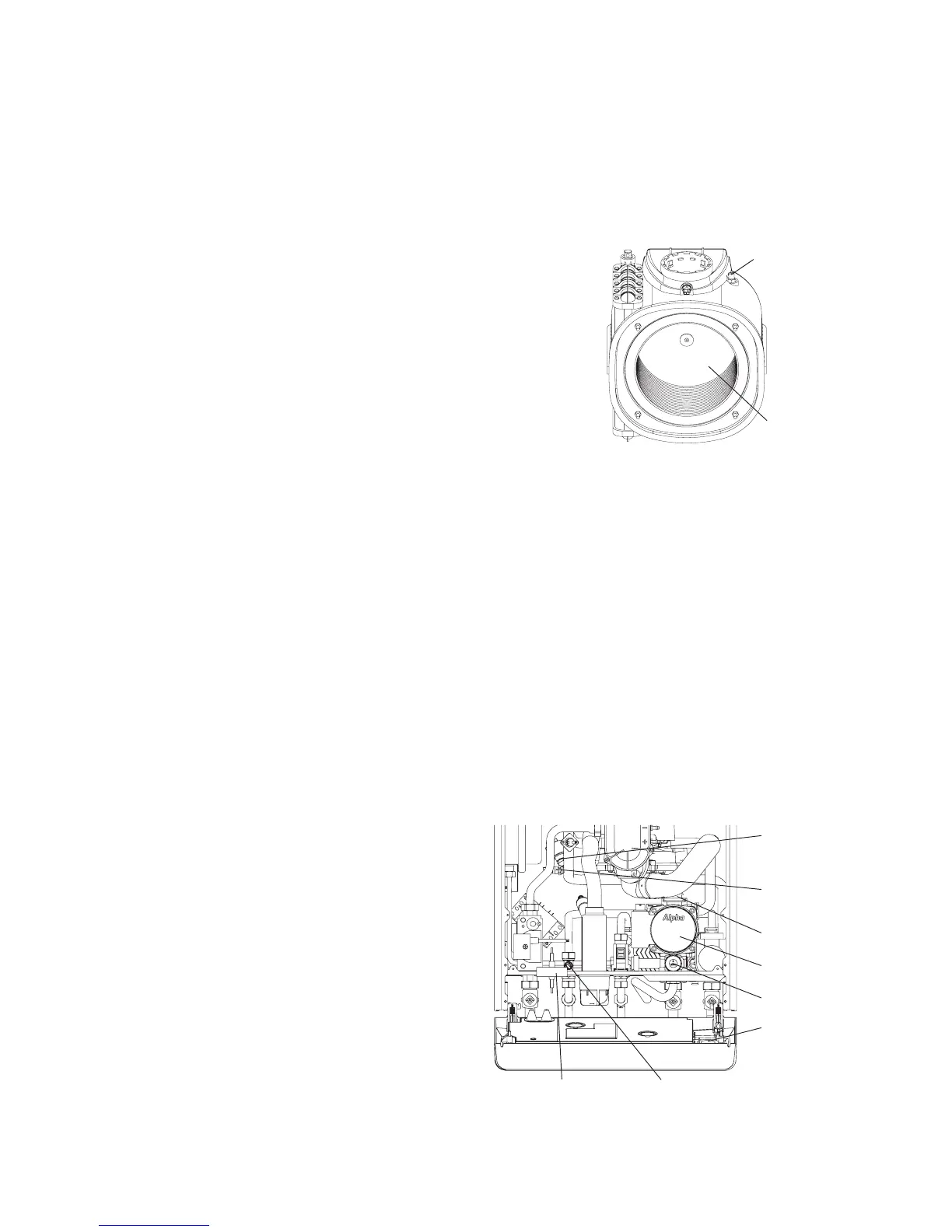
8.18 PRIMARY HEAT EXCHANGER - See Fig. 31 and 28
1. Gain access behind the room sealed chamber panel as described in Section 8.1
and drain the boiler heating circuit as described in Section 8.2.
2. Remove the burner as described in Section 7.2 (Routine Servicing).
3. Unplug the connections from the flue temperature sensor and thermal fuse.
See Fig. 28.
4. Disconnect the condensate drain pipe by pulling its rubber connector from the
heat exchanger.
5. Remove the screws securing the ignition generator, disconnect the earth lead
and remove the ignition generator.
6. Unplug the fan and remove it from the boiler.
7. Remove the heating flow and return pipe-retaining clips from the primary heat
exchanger and pull the pipes downwards from the heat exchanger connections.
8. Slide the heat exchanger downwards and forwards to disconnect from the flue connection and withdraw it from the boiler.
9. Re-assemble in reverse order, ensuring that new seals are used.
Lubricating the seals with the grease supplied will aid assembly.
10. Refill and pressurise the system. (Refer to Commissioning, Section 5.1).
8.19 COMBUSTION CHAMBER INSULATION
Gain access to the combustion chamber as described in Section 8.1.
Front panel insulation - see Fig. 27
1. Remove the electrodes from the combustion chamber front as described in Section 8.3.
2. Remove the four screws securing the burner.
3. Carefully remove the insulation.
Back panel insulation - see Fig. 31
1. Remove the combustion chamber front/burner assembly.
2. Remove the centre screw retaining the insulation.
3. Carefully remove the insulation, suction applied to the centre of the insulation will aid this.
Fit a new panel and re-assemble in reverse order.
8.20 PRESSURE GAUGE - Fig. 32
1. Gain access behind the casing and drain the boiler heating
circuit as described in Sections 8.1 and 8.2.
2. Remove the circlip securing the pressure gauge sensor
and withdraw the sensor.
3. Remove the main cable grommet in the bottom panel and
remove the sensor tube.
4. Depress the two lugs on the pressure gauge and push it
out of the control panel.
5. Fit the new gauge using a new 'O' ring on the connection if
necessary.
6. Refill and pressurise the system. (Refer to Commissioning,
Section 5.1).
Fig. 32
Alpha CD25X/28X - Component Replacement
Fig. 31
Thermal fuse
Back panel
insulation
Primary
pressure
switch
Primary
temperature
sensor
Automatic
air vent
Pump
Pressure
relief valve
Pressure
gauge
Cable grommet
DHW sensor