14750 East Nelson Ave #B
City of Industry, CA 91744
909-598-1077
www.alslighting.us
© 2021 Advantage Lighting Solutions
All Rights Reserved
Specications and dimensions
subject to change without notice
Rev:01/20/21
Page 3 of 4
INSTALLATION AND TECHNICAL INFORMATION EL SERIES EMERGENCY LIGHT
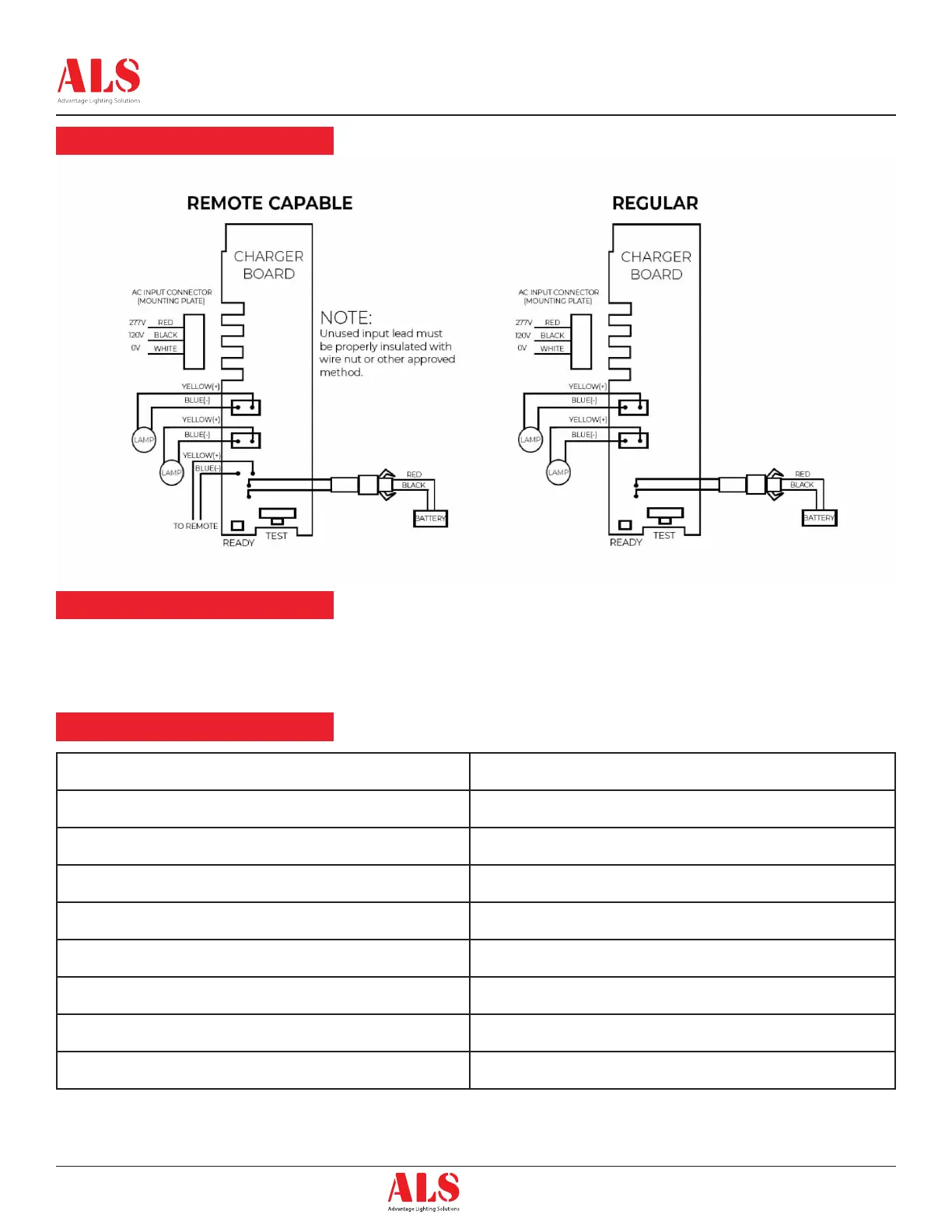
Wiring Diagram
Self-Diagnostics Test
Service Indication
Once the unit is properly installed according to the installation instructions sheet and AC power supplied, the dual color LED indicator will come ON
and the self-diagnostic test function will automatically initiate. The LED indicates the unit’s status. A STEADY GREEN LED indicates normal service;
FLASHING GREEN indicates the unit is testing; GREEN/RED FLASHING indicates the battery is charging; RED (in different combinations) would
indicate a service alert. Refer to the SERVICE INDICATION char below for more details. The LED would be OFF when the unit is in emergency mode.
Note:
Use 18-22 AWG standard
Wire to connect remote lamp
heads.
LED Indicator Status
One ash red Replace electronics
Two ash red Replace battery
Four ash red Replace lamp head board
Five ash red Replace Remote lamp or Remote lamp head disconnected
Steady red Battery Disconnected
Solid green Trickle Charge
Flashing green In Test
Red/Green ashing Hi Charge
 Loading...