14750 East Nelson Ave #B
City of Industry, CA 91744
909-598-1077
www.alslighting.us
© 2021 Advantage Lighting Solutions
All Rights Reserved
Specications and dimensions
subject to change without notice
Rev:01/20/21
Page 2 of 2
INSTALLATION AND TECHNICAL INFORMATION ES SERIES LED EXIT SIGN
Installation Instructions
Wiring Diagrams
Operation ( Battery Backup )
Testing
Maintenance
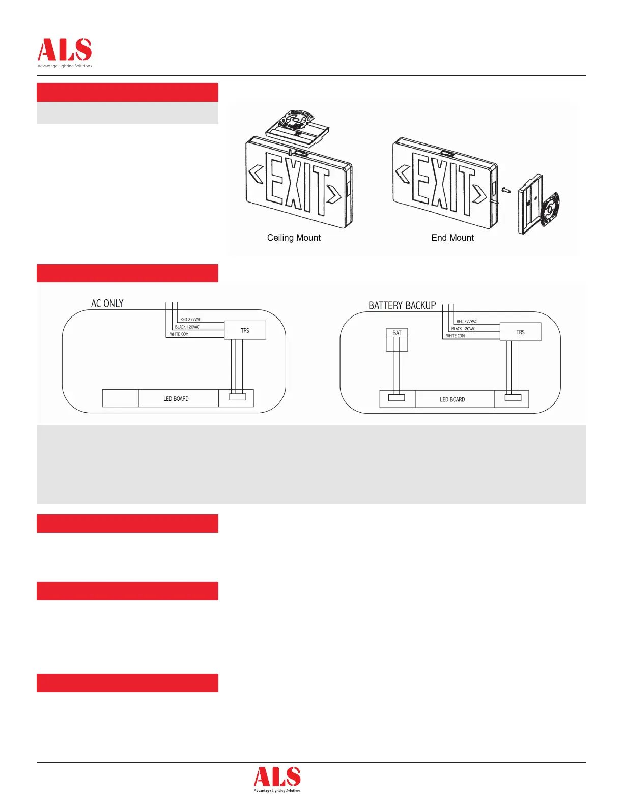
Ceiling and End Mount
1. Connect input as shown in wiring diagram
below and fasten canopy to the J-Box
bracket.
2. Snap housing to canopy.
3. Connect the battery (when applicable) to the
PC Board.
4. Secure faceplate to housing and remove the
proper arrow as required.
1. Loosen two set screws and remove metal
template.
2. Install EVA gasket on the back of the metal
template ( Note the direction of the arrow ).
3. Pull house supply wires through hole in
housing back and secure housing to junction
box with two mounting screws ( by others ).
4. Thread 1/2’’ conduit into the 1/2’’ hole.
5. Connect Black for Line, White for Neutral and
Bare Wire for Ground to complete the wiring.
6. Secure the xture on the metal template with
set screws.
1. Apply AC power to the unit. The LED Indicator should turn RED.
2. After the battery has been left to charge for 2 hours, test the unit by pushing the switch. The LED indicator turns OFF and the LED board stays ON.
3. When the switch is released, the LEDs turn OFF and the LED indicator turns back to RED.
National Electric Code (NEC) and NFPA life safety code regulations require that routine tests need to be performed as listed below:
Once every month, the unit needs to be tested for duration of 30 seconds. Push in and hold the test switch to perform this test. Once every 12
months, a full 90 minute (per UL requirements) test needs to be performed on the unit. Disconnect power to the unit and leave it in the emergency
mode. The LEDs should stay ON for atleast 90 minutes.
Always turn off AC power to the equipment before servicing. Servicing should be performed only by a qualified service technician. Use only
MANUFACTURER supplied replacement parts.
The battery supplied with the Battery Backup model requires no maintenance. However, it should be tested periodically (see TESTING) and replaced
when it no longer operates the connected xtures for the duration of a 30-second or 90-minute test. The battery supplied in this equipment has a life
expectancy of 5-7 years when used in a normal ambient temperature of 72ºF.
Note
Properly insulate the unused lead with a wire nut or other approved means.
Warning
Unused wire must be capped using enclosed wire nuts.
 Loading...