EasyManua.ls Logo

Alstom FKG1X - Page 171

Alstom FKG1X
274 pages
To Next Page IconTo Next Page
To Previous Page IconTo Previous Page
Loading...
Commissioning
Pre-
-
commissioning
inspections
G34
-
-0
01EN04
6/8
02--2011
© ALSTOM 2010. All rights reserved. Informat
ion contained in
this document is indicative only. No
representati
on or
warrant
y is
given or should
be
relied on that it is complete or correct or will apply to any particular project. This will depend on the technical and commercial circumstances. It is
provided without liabili
ty and
is subject to
change without notice. Reproduction, use or disclosure to
third parties, without express writt
en authority, is
strictly prohibited.
GRID
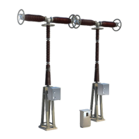
Test operations of disconnector(s)
(if applicable)
Introduction
The
me
as
ure
men
t
va
lu
es
de
man
de
d
he
rea
fter
ar
e
to
be
tak
en
du
rin
g
the
tes
t
an
d
in
sp
ec
tio
n
pr
og
ra
mme
pri
or
to
co
mmi
ss
io
ni
ng
an
d
ch
ec
ke
d
wi
th
the
va
l-
ues of the acceptance criteria” and checking points end of this sheet, then
en
ter
ed
in
the
pr
e-c
om
mis
sio
ni
ng
tes
t
rep
ort
(R
ES
...,
se
e
su
mma
ry
for
re
fer
-
ence) which should then be sent for approval to
ALSTOM Grid S.A. Cus-
tomer Service.
If,
ho
we
ve
r
,
the
va
lu
es
do
no
t
co
nfo
rm
wi
th
tho
se
for
es
ee
n
in
the
ac
ce
pta
tio
n
criteria or general characteristics, contact
ALSTOM Grid S.A. Customer
Service.
Closing time
Measure
,
on
each
pole,
the
time
lapse
betwee
n
curren
t
emissio
n
in
the
coil
of the closing contactor of the disconnector and the moment when
contacts touch in the pole.
Opening time
Measure
,
on
each
pole,
the
time
lapse
betwee
n
current
emission
in
the
dis-
connec
tor opening electro-magn
et
and the
moment when contacts
separa
te
in the pole.
Locking by means of
locks
Check that all keys required for locking are present.
Check that the
locking functio
ns of
discon
nector and earthing switch(es) are
ope
rati
ng
corr
ectl
y
,
in accor
dan
ce
with the
inte
rloc
kin
g diagra
m,
at both
ope
-
ning and closing of apparatus.
Position
signalis
ation
Che
ck
that
dis
con
nec
tor
pos
itio
n
ind
ica
tors
areopera
tingcorrec
tly
on
the
mi-
mic
diagram
.

Related product manuals