Step 4. If Steps
2
and
3
show normal function, connect
ohmmeter leads to collector and emitter. Read
on lowest ohms scale. Reverse leads and read
again. If reading is low and virtually unchanged
when ohmmeter leads are reversed, the transistor
has a short circuit between collector and
emitter.
Replacing PCB Components
Before removing PCB components for testing or replacement,
read and perform the following instructions.
1.
Solid
-
state components and PCB's may be damaged
by excessive heat. Use a small soldering iron with
a
118.inch diameter chisel tip and use small
-
diameter
60140 rosin
-
cored solder.
2.
Remove components by placing soldering iron on
component lead on conductor side of PCB and pull
out lead. Avoid overheating the conductor.
CAU
I
ION
surface plated with solder and laminated
to the board. Too much pressure or over
-
heating may lift the conductor from the
P>n
1
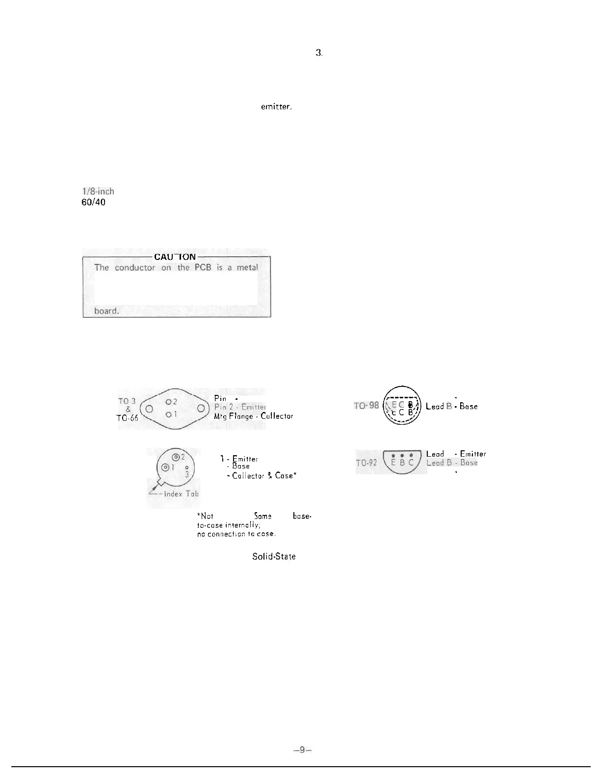
-
Base
70-66
Mtg
Flange. Ccillector
Lead
1
-
Emitter
TO
-
5
Lead
2
-Base
Lead
3
-Collector
P
Case*
3.
If component is faulty or damaged, clip leads close to
component and then unsolder leads from board. With
-
draw leads from component side.
4.
Clear solder from circuit board holes before inserting
leads of new component. Heat solder remaining in
hole, remove iron and quickly insert a pointed non
-
metallic object, such as a toothpick, from conductor
side.
5.
Shape new component leads and clip to proper
length. Lead shape should provide stress relief for
component. Insert leads in holes, observing same
polarity or orientation of removed component. Apply
heat and solder on conductor side.
Repairing Fractured or Damaged PCB Conductor
If a conductor is fractured, damaged or lifted from the cir
-
cuit board, a recommended method of repair is to solder a
section of good conducting wire along the damaged area and
then seal with epoxy.
,-----.,
Leod
E
-
Emitter
.
. .
)
Lead
C
-
Collector
0
\\!
C
B:
Lead
5
-
Bose
.__c'
Lead
E
-
Emitter
Leod
C
-
Collector
'Not all
types.
Some
have
bose.
to-cose
internally:
others
hove
no
connection
to
cose.
Figure
9.
Typical Solid.State Component Configurations
 Loading...