2018 FORD F-150 5.0L COMPRESSED NATURAL GAS CONVERSION SYSTEM INSTALLATION INSTRUCTIONS
2018 F-150 5.0L INSTALLATION MANUAL
Page 31
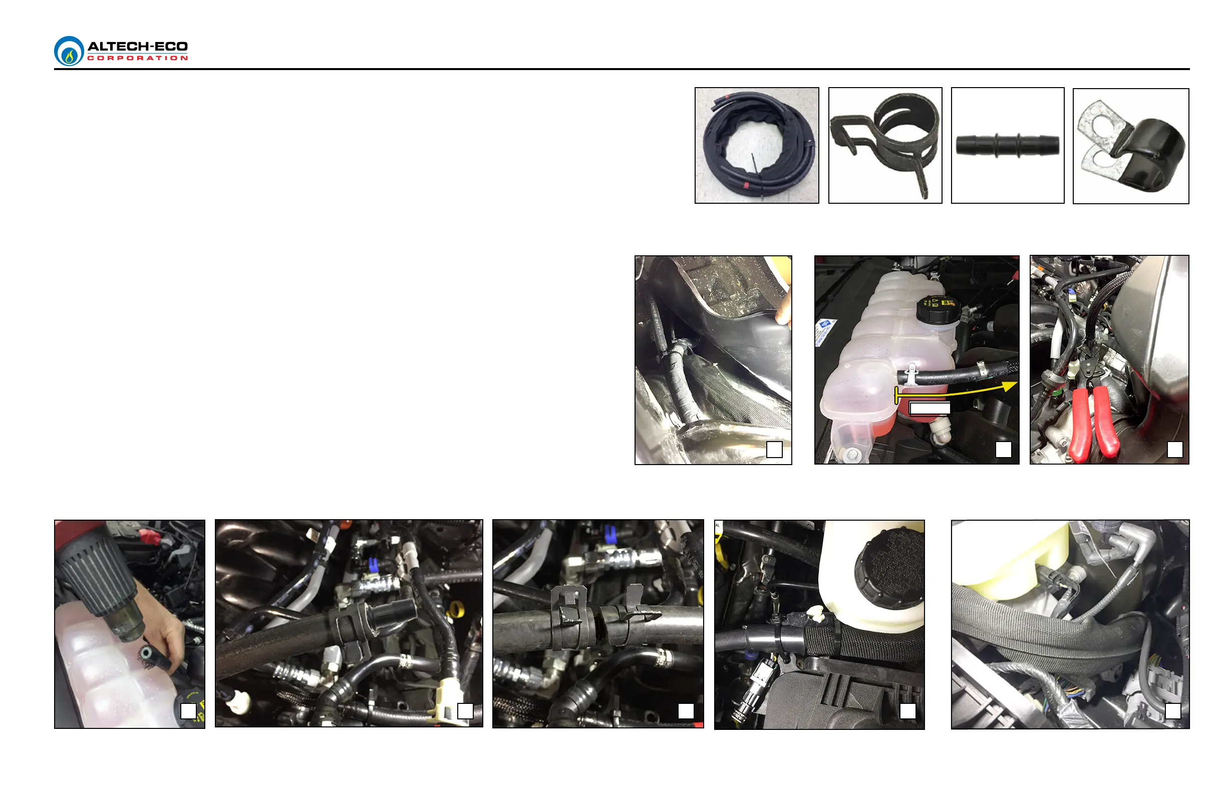
COOLANT HOSE ROUTING
1. Depressurize the coolant system by removing the coolant reservoir cap. DO NOT REMOVE COOLANT
CAP IF ENGINE IS HOT!
1. Lay the CNG coolant hoses from front to back along the ground below the truck (driver side). On
engine side, feed the CNG coolant hose up through wheel well behind mud cover (Fig. A). In engine
compartment pull coolant hose up and over to middle of engine. Lay hose down for later connections.
2. Locate the Ford coolant hose connected to coolant reservoir (Fig. B). Measure and mark the Ford
coolant hose at 15 1/2” from reservoir hose end. Crimp the hose below mark and cut the hose (Fig. C).
With a heat gun melt the hose meshing on both ends to form around hoses (Fig. D).
3. Insert one straight connector (80651) per each cut hose end, two connectors in total (Fig. E).
4. Slide a hose clamp on each end of all 4 hose ends (CNG and Ford) to get ready for nal connections.
5. The CNG coolant hose identied with colored tape connects to the Ford coolant hose coming out of
the engine and the IN port on CNG regulator. Use clamp pliers to secure clamp over connection with
straight connector (Fig. F).
6. The other CNG coolant hose connects to the coolant hose coming out of reservoir and the OUT port
on CNG regulator. Use clamp pliers to secure clamp over connection with straight connector (Fig. F).
7. Remove hose crimp from hose. Pull slack on hose from under vehicle to engine compartment, then zip
tie the CNG coolant hoses to lter air box. Disconnect the Ford white clip and zip tie it along with CNG
coolant hose to box (Fig. G).
8. Under the vehicle, route the CNG coolant lines above frame in same location as Ford wire harness.
(Fig. G-Q). Route coolant hoses through bed oor grommet.
9. Secure hoses with zip ties and a p-clamp (Fig. G-Q).
10. Connect coolant hoses to regulator (same as steps 5 & 6) and secure with hose clamps (Fig P).
11. Check for leaks when conversion system is completed and engine can be started. Add coolant to
reservoir as needed.
CNG Coolant Hoses Hose Clamp Straight Connector P-Clamp
D E F HG
BA C
15 1/2”
 Loading...