Selecting fixed/intermittent current
Operation with fixed or intermittent currents may be
chosen after the unit is turned on and the RTD type
has been selected.
Fixed currents are indicated by
Intermittent currents are indicated by
To keep the excitation selection: Wait 3 seconds To change the
excitation selection: Press the STORE pushbutton Note: Cu
indicates Current while selecting fixed or intermittent currents.
Hint: Choose intermittent excitation only when device to be
calibrated uses intermittent currents. Most devices require that
fixed current operation is selected.
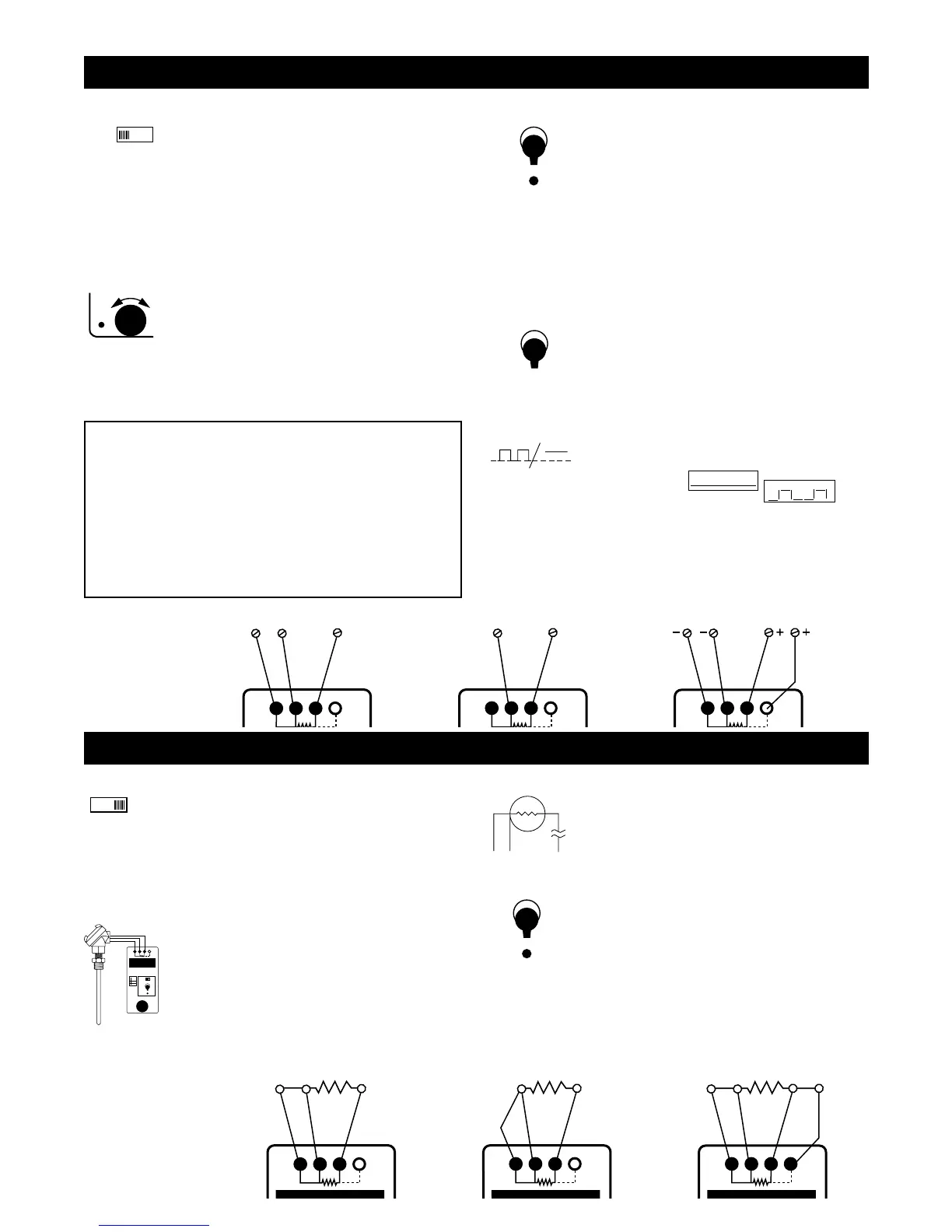
Simulate RTD or resistance
Simulate
1) Set up the Model 211 for the correct RTD type
and temperature scale (°C or °F).
2) Disconnect the input wires from the device to be
calibrated or checked.
3) Connect the Model 211 to the device to be
calibrated, being careful to observe proper
connections for 2, 3 or 4-wire hookups.
4) Adjust the digital pot to the desired output value.
Output
Whenever SIMULATE mode is selected the word
SIM will appear on the LCD. SIM will flash when
the Model 211 is measuring the external excitation
current and will be steady when accurately simulat-
ing a resistance. To change the output value, turn
the speed sensitive digital pot. Turning the pot
slowly will cause a gradual change in the output. A
faster change will occur when the pot is turned
faster. A filter circuit limits response when the pot is
turned too fast. This function operates in all three
output positions (HI, SET & LO).
Store
1) Switch to HI (or LO).
2) Turn the digital pot to desired value.
3) Press STORE. The LCD will flash once indicating
that the value has been stored
If a value is in the SET position and you want that
value in HI or LO, press and hold the STORE button
while moving the switch to HI or LO. The LCD will
flash once indicating that the value has been stored.
Release the STORE button. When there is no exci-
tation current or the current is less than 0.09 mA
SIM will flash on the LCD. “QUIK-CHEK” values
may be stored with SIM flashing.
Instantly recall temperatures
Any time you need a stored value just throw the
“QUIK-CHEK” switch. Any value in the RTD range
may be stored in HI & LO. The Model 211 remem-
bers the HI, LO and SET values for you with the
power on or off. The resolution of the stored value is
based on the excitation from the receiver.
Read an RTD sensor
Read
1) Set up the Model 211 for the RTD, Ohms and
temperature scale (°C or °F).
2) Disconnect the wires from the resistance sensor
to be read or checked.
3) Connect the Model 211 to the sensor to be
measured, being careful to observe proper con-
nections for 2, 3 or 4 wire hookups.
4) Display present reading, Maximum or Minimum
temperature.
Input
Whenever READ mode is selected the word READ
will appear on the LCD. The Model 211 can mea-
sure temperatures in two ranges with resolution of
0.1° and 1°. The display is updated twice per
second to continuously track fast moving
temperatures. Using three or four wire hookups
provides accurate readings in long cable runs.
Hookup —
Simulate an
RTD or
resistance
Open RTDS
The Model 211 checks for open or high resistance
connections. Open or burned out RTDS are indicat-
ed by - - - - - on the display. Temperatures out of
range for the RTD selected will be indicated by
OVER and UNDER on the display.
MIN/MAX
To read the Maximum or Minimum temperature
since READ mode was entered, simply switch to
MAX or MIN. The value will appear on the LCD
along with the word MAX or MIN. The MAX/MIN
values are automatically updated and may be
viewed at any time without disturbing the other
values. Press RESET and the Model 211 will flash
the display once to indicate it has transfered the
present temperature into both MAX and MIN and
will update them as the measured temperature
changes.
Hookup —
Read an RTD
or resistor
Note: SIM flashing on the LCD indicates that the excitation
current is missing, out of range or is intermittent. Check to see
that the device being calibrated has operating power and that the
211 is properly connected. Also check the manual for the device
to make sure that the excitation current is in the range of 0.090 to
5.800 milliamps.
Note: Some “smart” transmitters and scanning recorders or indi-
cators use intermittent currents to measure RTD’s. Try putting
recorders into a calibrate mode or lock them into one channel.
The Model 211 can be configured to accept intermittent excitation
with mininum 125 msec fixed current at a mininum repetition rate
of 1/sec (see Operating with intermittent currents).
 Loading...