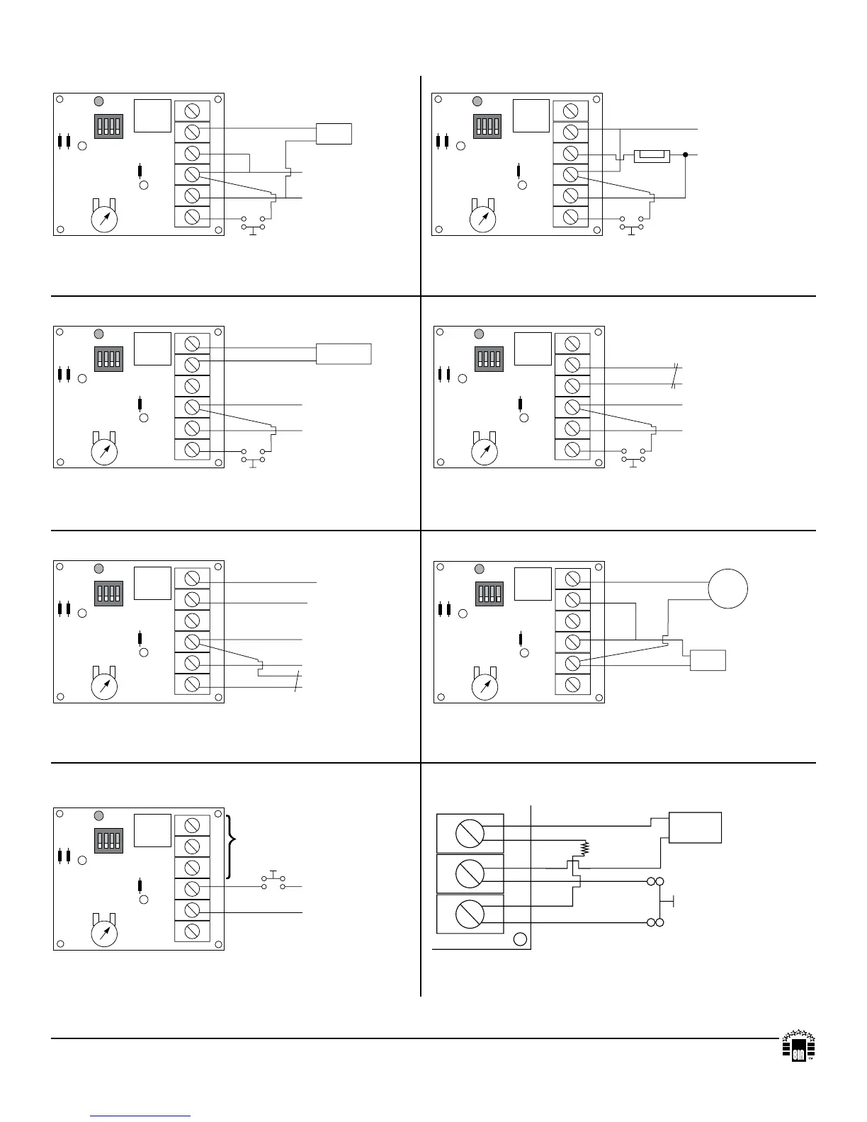
6062 Typical Applications:
Fig. 1 - Timed Door Annunciator:
ForthisapplicationSwitch#1andSwitch#4
should be in the OFF position.
Fig. 5 - Timed Door Strike:
ForthisapplicationSwitch#1shouldbeintheOFF
positionandSwitch#4shouldbeintheONposition.
Fig. 2 - Guard Tour Supervisory Timer:
ForthisapplicationSwitch#1andSwitch#4
should be in the OFF position.
Fig. 6 - Timed Shunt for a Door: Use to bypass alarm contacts.
ForthisapplicationSwitch#1shouldbeintheOFF
positionandSwitch#4shouldbeintheONposition.
Fig. 3 - Swinger Eliminator:
ForthisapplicationSwitch#1shouldbeintheOFFposition
andSwitch#4shouldbeintheONposition.
Fig. 7 - Bell Cut Off Timer:
ForthisapplicationSwitch#1shouldbeintheONpositionand
Switch#4isnotusedinthisapplication.
Fig. 8 - Closed Circuit Trigger Option:
TRG -- +
Closed
Circuit
Contact
Pull up
Resistor
Power
Supply
+
---
Fig. 4 - Delay Timer: Use for Door Ajar Alarm, Delayed
Activation of Digital Dialer, Defrost Cycle Timer, etc...
ForthisapplicationSwitch#1shouldbeintheONposition
andSwitch#4isnotusedinthisapplication.
MEMBER
For this application a resistor [for 12VDC - 2K (2,000 ohm)
or for 24VDC - 4.7K (4,700 ohm)] must be installed as shown
(resistor not supplied).
Altronixisnotresponsibleforanytypographicalerrors.
14058thStreet,Brooklyn,NewYork11220USA,718-567-8181,fax:718-567-9056
website:www.altronix.com,e-mail:info@altronix.com,LifetimeWarranty,MadeinU.S.A.
II6062 - Rev. 032211 C22K
TRG -- + NO C NC
1
ON
ON
1 2 3 4
OFF
15
CUT J3 FOR RESET
ON POWER-UP
TRIG CONTROL
12V / 24V
SEC. / MIN.
RELAY CONTROL
CHIME
Pos (+) and Neg (--
terminals constant
12VDC or 24VDC
Normally Open
Door Contacts
+
---
+
---
4
3
2
1
J3
CUT J2 FOR DELAY PULSE J2
CUT J1 FOR REPEAT J1
45
60
TRG -- + NO C NC
1
ON
ON
1 2 3 4
OFF
15
CUT J3 FOR RESET
ON POWER-UP
TRIG CONTROL
12V / 24V
SEC. / MIN.
RELAY CONTROL
Pos (+) and Neg (--
terminals constant
12VDC or 24VDC
Normally Open
Door Contacts
Door Strike
+
---
+ -- -
4
3
2
1
J3
CUT J2 FOR DELAY PULSE J2
CUT J1 FOR REPEAT J1
45
60
TRG -- + NO C NC
1
ON
ON
1 2 3 4
OFF
15
CUT J3 FOR RESET
ON POWER-UP
TRIG CONTROL
12V / 24V
SEC. / MIN.
RELAY CONTROL
DIALER OR
TRANSMITTER
Pos (+) and Neg (-- )
terminals constant
12VDC or 24VDC
Normally Open
Switch Contacts
+
---
4
3
2
1
J3
CUT J2 FOR DELAY PULSE J2
CUT J1 FOR REPEAT J1
45
60
TRG -- + NO C NC
1
ON
ON
1 2 3 4
OFF
15
CUT J3 FOR RESET
ON POWER-UP
TRIG CONTROL
12V / 24V
SEC. / MIN.
RELAY CONTROL
Pos (+) and Neg (--
terminals constant
12VDC or 24VDC
Door Contacts
Protective
Circuit
+
---
4
3
2
1
J3
CUT J2 FOR DELAY PULSE J2
CUT J1 FOR REPEAT J1
45
60
Normally Open
Switch Contacts
TRG -- + NO C NC
1
ON
ON
1 2 3 4
OFF
15
CUT J3 FOR RESET
ON POWER-UP
TRIG CONTROL
12V / 24V
SEC. / MIN.
RELAY CONTROL
Closed
Circuit
Zone on
Control Panel
Pos (+) and Neg (--
terminals constant
12VDC or 24VDC
Protective
Circuit
+
---
4
3
2
1
J3
CUT J2 FOR DELAY PULSE J2
CUT J1 FOR REPEAT J1
45
60
TRG -- + NO C NC
1
ON
ON
1 2 3 4
OFF
15
CUT J3 FOR RESET
ON POWER-UP
TRIG CONTROL
12V / 24V
SEC. / MIN.
RELAY CONTROL
Use appropriate contacts
to reporting devices
Normally Open
Triggering Device
Pos (+) and Neg (--
terminals constant
12VDC or 24VDC
+
---
4
3
2
1
J3
CUT J2 FOR DELAY PULSE J2
CUT J1 FOR REPEAT J1
45
60
TRG -- + NO C NC
1
ON
ON
1 2 3 4
OFF
15
CUT J3 FOR RESET
ON POWER-UP
TRIG CONTROL
12V / 24V
SEC. / MIN.
RELAY CONTROL
Bell
or
Siren
+
---
4
3
2
1
J3
CUT J2 FOR DELAY PULSE J2
CUT J1 FOR REPEAT J1
45
60
Bell
Output
Control Panel
12VDC or 24VDC
 Loading...