ReServ2 - 3-
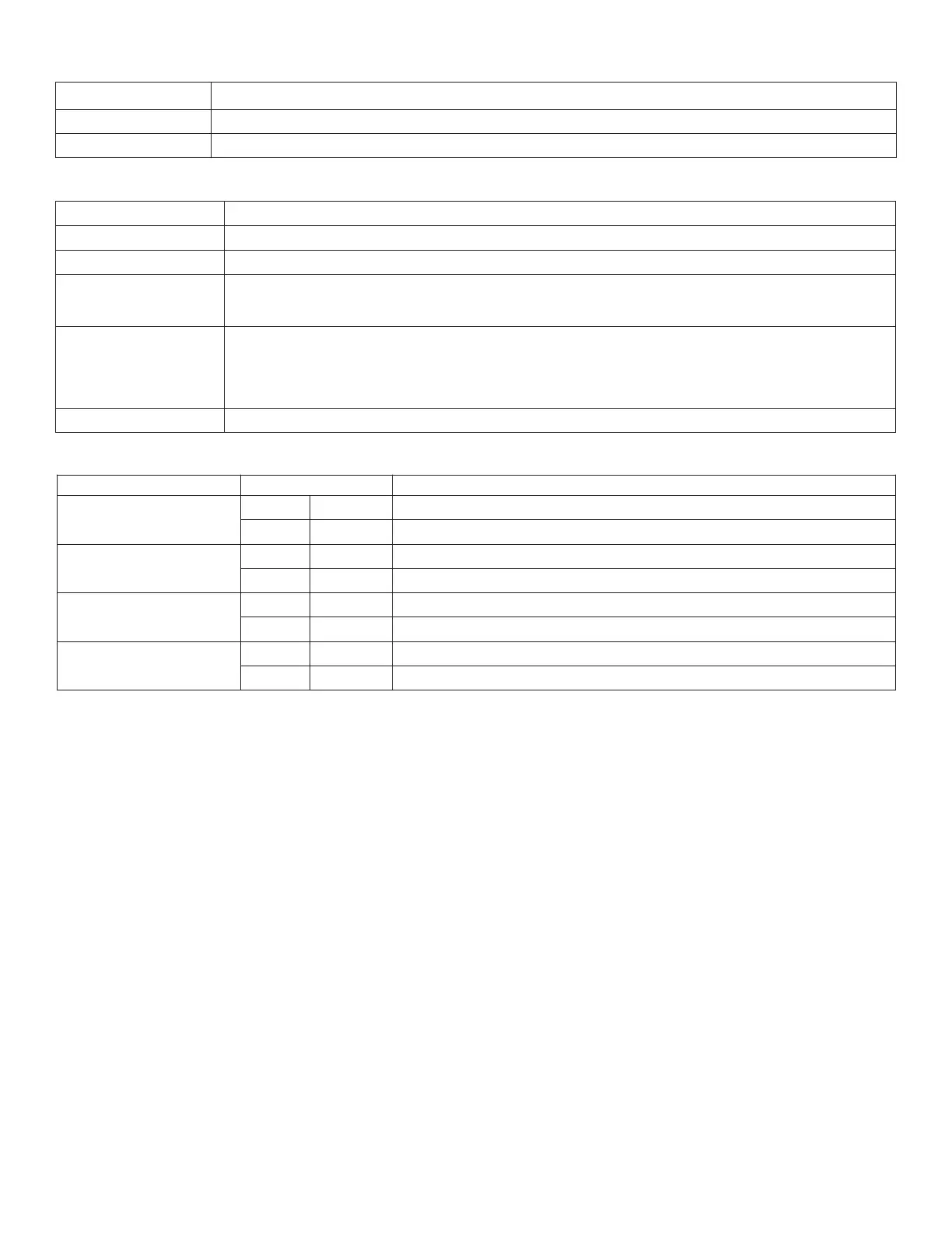
Stand-by Specifications:
Terminal Identification:
LED Diagnostics:
Stand-by Battery 4 amp (100VA) max. load at 24VAC
2 - 12VDC/7AH 45 minutes
2 - 12VDC/12AH 90 minutes
Terminal Legend Function/Description
L, G, N Connect 115VAC to these terminals: L to Hot, N to Neutral, G to ground (if used).
1-16 24VAC outputs.
AC Fail
NO, C, NC
Used to notify loss of AC power, e.g. connect to audible device or alarm panel. Relay normally
energized when AC power is present. Contact rating 1 amp @ 28VDC.
Battery Fail
NO, C, NC
Used to indicate low battery condition, e.g. connect to alarm panel. NO, C, NC Relay normally
energized when DC power is present. Contact rating 1 amp @ 28VDC.
Low battery threshold:
24VDC output threshold set @ approximately 21VDC.
--- B AT + Stand-by battery connections. Maximum charge rate .5 amp.
LED LED State Description
AC (Green)
ON ----- Normal operating condition.
----- OFF Loss of AC. Stand-by batteries are supplying power.
24VAC Power Outputs
(Red)
ON ----- Normal operating condition.
----- OFF Loss of 24VAC output power.
Low Battery
ON ----- Stand-by batteries are low.
----- OFF Normal operating condition.
Shutdown
ON ----- Loss of 24VAC output power. Discharged stand-by batteries.
----- OFF Normal operating condition.
 Loading...