SERVICING
26
1. Remove doors, control panel cover, etc. from unit being
tested.
With power ON:
2. Using a voltmeter, measure the voltage across terminals
L1 and L2 of the contactor for single phase units, and
L3, for 3 phase units.
3. No reading - indicates open wiring, open fuse(s) no
power or etc. from unit to fused disconnect service.
Repair as needed.
4. If incoming voltage is within the range listed in the chart
below, energize the unit.
5. Using a voltmeter, measure the voltage with the unit
starting and operating to determine if voltage is within
the range listed in the chart below.
6. If the voltage falls below the minimum voltage, check
the line wire size. Long runs of undersized wire can
cause low voltage. If the wire size is adequate, notify
the local power company regarding either low or high
voltage.
208/230 198 253
1. Check wiring visually for signs of overheating, damaged
insulation and loose connections.
2. Use an ohmmeter to check continuity of any suspected
open wires.
3. If any wires must be replaced, replace with comparable
gauge and insulation thickness.
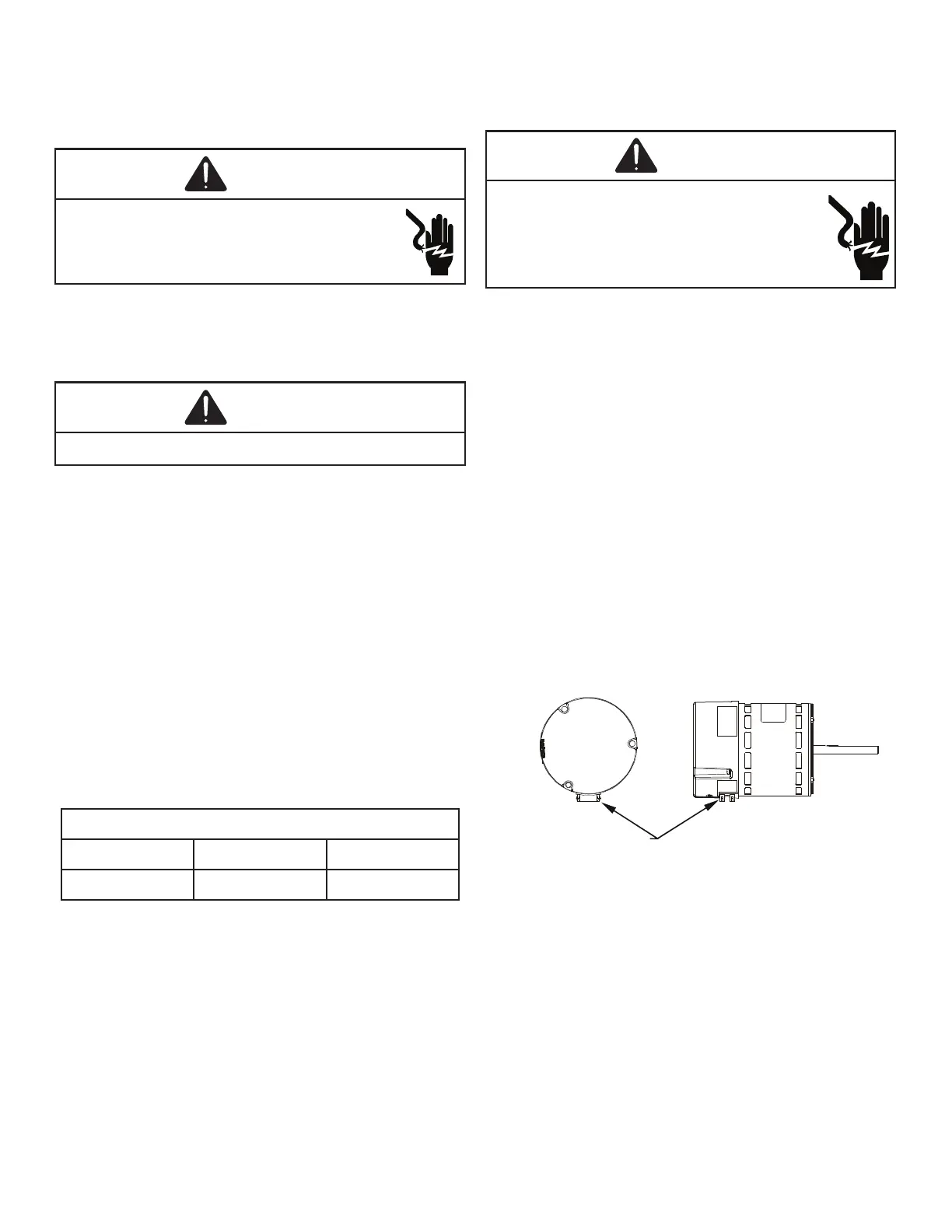
If the unit is in the upow position, there is no need to
rotate the motor. If the unit is in the downow position,
loosen motor mount and rotate motor as shown in the
AVPTC Motor Orientation gure below. Be sure motor is
oriented with the female connections on the casing down.
If the motor is not oriented with the connections down,
water could collect in the motor and may cause premature
failure.
FEMALE CONNECTIONS
SIDE VIEW
WARNI NG
SOFTWARE VER.
TOP
FRONT VIEW

 Loading...