SERVICING
33
1. Connect voltmeter to lugs (L2) and (C).
2. With power ON, provide a call for cool or heat pump to
energize the on-board compressor contactor/relay.
3. Measure voltage across on-board compressor
contactor/relay contacts.
A. No voltage indicates the contacts are closed and the
contactor/relay is functioning properly.
B. A reading of approximately half of the supply voltage
(example: 115VAC for 230VAC) indicates the relay
is open. Replace UC control if relay does not
close.
1. Measure voltage between black and brown motor leads.
This should measure 208/230 volts depending on your
power supply.
2. If voltage is present proceed to check fan relay contacts
and voltage.
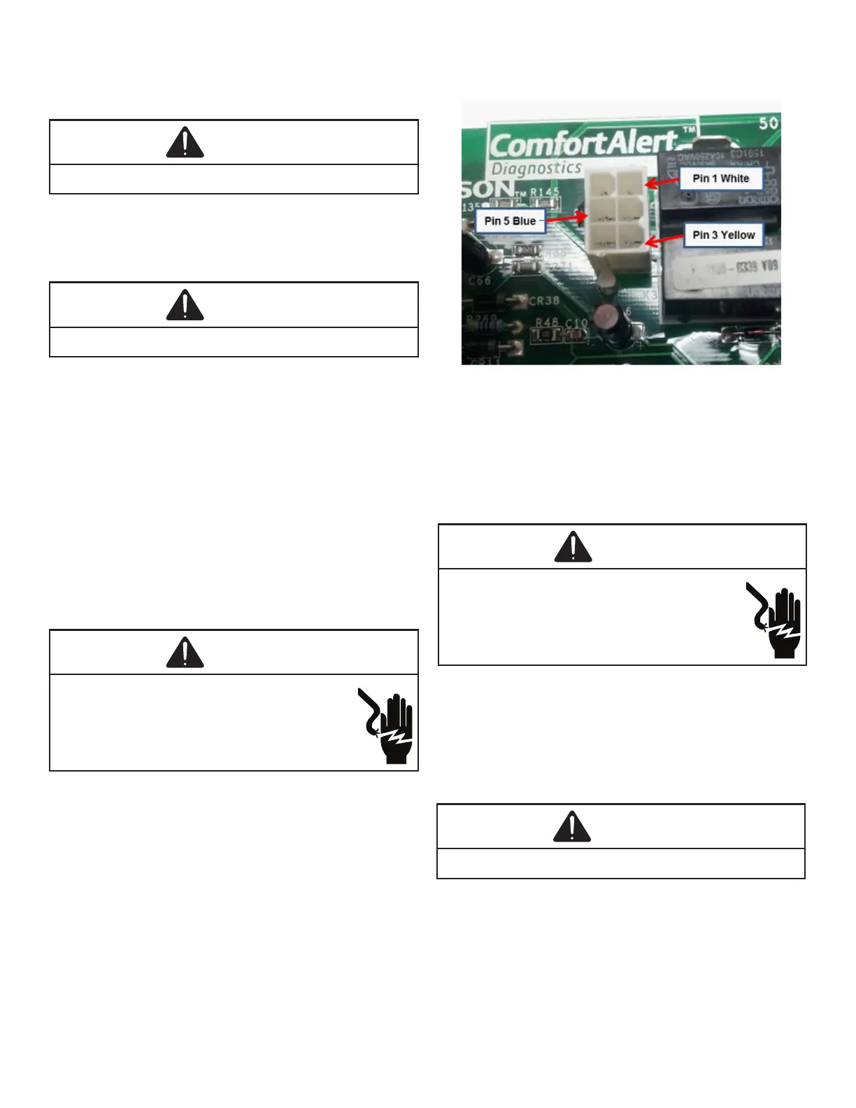
1. Disconnect fan motor harness from plug on the UC
board.
2. Energize the system in low stage and check voltage:
• Pin 5(Blue wire) to Pin 3(Yellow wire) = 24VAC
3. Energize the system in high stage and check voltage:
• Pin 5(Blue wire) to Pin 3(Yellow wire) = 24VAC
• Pin 5(Blue wire) to Pin 1(White wire) = 24 VAC.
4. If voltage is present at these pins plug harness into plug
on PC board and check voltages at motor to test for
broken wires.
5. If all voltages are present motor is defective and needs
to be replaced.
1. Disconnect the motor leads from 6-circuit fan motor wire
harness.
2. Connect a voltmeter between circuit 3 and circuits 2
(low speed) or 1 (high speed).
3. Energize the system at low or high stage.
4. The measured voltage between circuit 3 and circuits
2 or 1 should be approximately 0VAC, which indicates
the relay contacts are closed. A voltage measurement
of approximately 115VAC indicates the relay is open.
Replace the control if the relay checks open when it
should be closed.

 Loading...