SERVICING
34
The Copeland Comfort Alert™ diagnostics are fully
integrated into the unitary (UC) control. The UC control
and integrated Comfort Alert™ diagnostics provide around-
the-clock monitoring for common electrical problems,
compressor defects and broad system faults. If a problem
is detected, LED indicators ash the proper alert codes to
help you quickly pinpoint the problem.
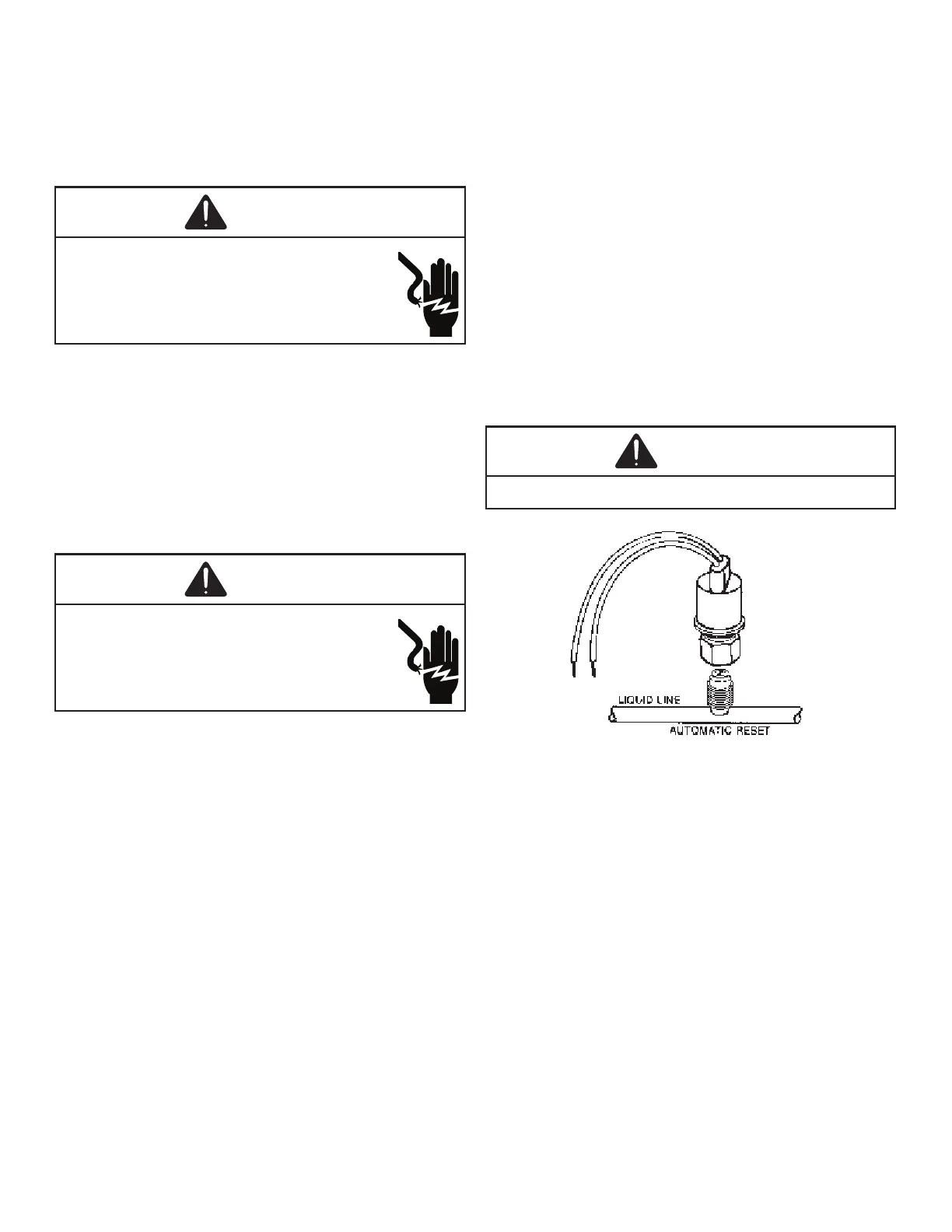
The high pressure control capillary senses the pressure
in the compressor discharge line. If abnormally high
condensing pressures develop, the contacts of the control
open, breaking the control circuit before the compressor
motor overloads. This control is automatically reset.
1. Connect refrigerant gages to unit.
2. Disconnect power to outdoor unit.
3. Remove control panel cover.
4. Disconnect black wire from condenser fan motor (single
stage units) or remove plug from control board on 2
stage units. Note: Tape or isolate black wire to prevent
possible short.
5. Apply power to unit and set thermostat to cool and set
for all for cool.
6. High pressure switch should open at 610 PSIG +/- 10
PSIG and close at 420 PSIG +/- 25 PSIG
7. If high pressure switch does not operate in these
parameters replace switch.
1. Connect refrigerant gages to unit.
2. Disconnect power to indoor unit.
3. Remove control panel cover.
4. Disconnect black wire from evaporator fan motor (single
stage units) or remove plug from control board on 2
stage units. Note: Tape or isolate black wire to prevent
possible short.
5. Apply power to unit and set thermostat to heat and set
for call for heat.
6. High pressure switch should open at 610 PSIG +/- 10
PSIG and close at 420 PSIG +/- 25 PSIG
7. If high pressure switch does not operate in these
parameters replace switch.
With power ON:
The low pressure control senses the pressure in the
suction line and will open its contacts on a drop in
pressure. The low pressure control will automatically reset
itself with a rise in pressure.
1. Connect refrigerant gages to unit.
2. Disconnect power to indoor unit.
3. Remove control panel cover.
4. Disconnect black wire from evaporator fan motor (single
stage units) or remove plug from control board on 2
stage units. Note: Tape or isolate black wire to prevent
possible short.
5. Apply power to unit and set thermostat to cool and set
for a call for cool.
6. Low pressure switch should open at 21 PSIG, and auto
reset (close) at approximately 50 PSIG.
7. If low pressure switch does not operate in these
parameters replace switch.

 Loading...