Introduction
TRONEX – Connects to the circuit
We take pleasure to welcome you to try out this ready-to-use electronic circuit kit
suitable for children of 8 years old and up. “You’ll be amazed” to find what you can
learn as the experiment is a realistic concept of electronics and electricity. It will
definitely enable you to learn about the necessary electronic components, circuits, and
theories as well as the basic electronics principles – electricity, voltage, current,
resistance, magnetism, other electrical circuit and theory.
It is alright if you have no knowledge about electronics and do not fully understand
how all the experiments work. Once you get started you will be able to build your
understanding through experimenting and maybe trying out some interesting
experiments on your own.
This electronic circuit kit contains more than 72 experiments, and it is smartly designed
that the main circuit board unit has all the relevant electronic components included. All
you have to do is simply connect the wires according to the wiring sequence of each
experiment and follow the steps one by one. Once connected the circuit will activate
and function.
Remember this is not a one-time experiment. The more you spend on building the
experiments the better knowledge you will gain. You will never get bored but totally
engaged as you will discover more new exciting experiments for a few years to come.
Have a great electrifying experience !!!
WARNING: Only for use by children aged 8 years and older
72+ EXPERIMENTS
COMPONENTS IN THIS KIT
Description Quantity
72 in 1 Circuit Board Unit
Magnetic pole
Connecting wire
Instruction Manual
WARNING
Adult supervision and assistance is required.
This unit is only for use by children aged 8 years and older.
Not suitable for children under age 3 years old due to small part(s)
and component(s) – CHOKING HAZARD.
Read and follow all instructions in the manual before use.
This toy contains small parts and functional sharp points on
components. Keep away from children under age 3 years.
4 x 1.5V AA (LR6) size batteries are required (not included)
Please retain the information and this manual for future reference.
CAUTION !
Before setting up any experiment, please double check and make sure
all wiring connections you have made are correct before inserting the
batteries and switching on the unit as failure may result in damage to
components or circuit board unit.
When experiment is finished, make sure the batteries are
disconnected and switch off the unit before you clear away the wires.
Do not apply any components or parts to the experiment other than
those provided with this kit.
If this product malfunctions or "locks up", try switching off and back
on again or removing and re-inserting batteries.
BATTERY INFORMATON
Use 4 x 1.5V AA (LR6) size batteries (not included)
For best performance, always use fresh batteries and remove batteries
when not in use
Batteries must be inserted with the correct polarity
Do not use rechargeable batteries
Non-rechargeable batteries are not to be recharged
Re-chargeable batteries are only to be charged under adult supervision
Re-chargeable batteries are to be removed from the toy before being
charged
Different types of batteries or new and used batteries are not to be mixed.
Exhausted batteries are to be removed from the toy
The supply terminals are not to be short-circuited
Only batteries of the same or equivalent types are to be used
Do not dispose of the batteries in fire
Do not mix old and new batteries
Do not mix alkaline, carbon zinc and re-chargeable batteries
WIRING SEQUENCE AND CONNECTION
Ensure all wires are correctly connected to the numbered spring terminals
of the main circuit board unit as stated wiring sequence of each experiment
Bend the spring terminal over and insert the exposed shiny conductor part
of wire into spring terminal. Make sure the wire is securely connected to
spring terminal.
For example if the wiring sequence is 4-33, 1-10-32-35, 2-12, then
connect a wire between spring terminal 4 and 33; and then connect a wire
between spring terminal 1 and 10, and a wire between spring terminal 10
and 32, and a wire between spring terminal 32 and 35; and finally
connect a wire between spring terminal 2 and 12. This is an example for
reference only, not an exact circuit connection in the experiment.
If the circuit does not work, you can check the wire and spring terminal
connection whether it is not well connected or insulated plastic part of the
wire is inserted to spring terminal.
1
EXPERIMENT
Color filter
• Complete all wiring connections as indicated in the
sequence. By switching ON, the color filter will be
activated for rotating.
• Complete all wiring connections as indicated in the
sequence. By switching ON, the color filter will rotate,
and red LED will light up; By switching OFF, the color
filter will stop, and red LED will extinguish.
•
Complete all wiring connections
as indicated in the sequence. By
switching ON, both red LED and green LED will light up.
By switching OFF, both LED will extinguish.
• Complete all wiring connections
as indicated in the sequence. By
switching ON, green LED will light up, and the capacitor
will be charged. By switching OFF, green LED will
extinguish. And then press the push switch. Capacitor
will discharge to red LED and make it bright for a while.
When the discharge ends, the capacitor has used up
stored electricity and thus red LED will extinguish.
• Complete all wiring connections as indicated in the
sequence. By switching ON, LED will light up. By
switching OFF, the LED will extinguish.
•
Complete all wiring
connections as indicated in
the sequence. By switching ON, both red LED and large
green LED will light up. When pressing on the push
switch, red LED will not light up, but large green LED will
light up. This circuitry can be used for switching between
weak light and strong light.
Wiring Sequence
2-6, 5-77,
76-1
4
EXPERIMENT
Diode and capacitor charging/discharging
Wiring Sequence
2-76,
50-51-77, 75-49-45, 39-46,
37-52, 1-36-38-74
1. Color filter
2. Color filter in parallel with red LED light
3. Red and green LED light
4. Diode and capacitor charging/discharging
5. LED light
6. Basic circuitry of LED light
7. Timer electric motor
8. Time-delay electric motor
9. Sound control color filter
10. Touch-mode motor
11. Alternate working of LED light and
electric motor
12. Speed-adjustable electric motor
13. Direction-change indicator
14. Rain indicator
15. LUX indicator
16. Connection indicator
17. Light control stop-and-
rotate electric motor
18. Magnet control stop-and-
rotate electric motor
19. Manual control stop-and-
rotate electric motor
20. Light control extinguish-and-light LED
21. Magnet control extinguish-and-light LED
22. Manual control extinguish-and-light LED
23. Double-Switch control LED light
24. Practical super dimmable LED light
25. Super manual control delayed LED
26. Super magnetic activated delayed LED
27. Super touch-to-lit delayed LED
28. light control activated LED light
29. Super LED light activated by darkness
30. Light control extinguish-
and-light super LED light
31. Adjustable and blow-able super LED light
32. Manual control extinguish-
and-light super LED light
33.
Touch control motor dory sound with red LED
34.
Touch control motor dory sound with green LED
35. Touch control ship sound with LED
36.
Magnet control motor dory sound with red LED
37.
Magnet control motor dory sound with green LED
38. Magnet control ship sound with LED
39.
Magnet control electronic metronome with LED
40.
Manual control electronic metronome with LED
41.
Manual control motor dory sound with red LED
42.
Manual control motor dory sound with green LED
43. Manual control ship sound with LED
44. Manual control delayed motor dory sound
45. Magnet control delayed motor dory sound
46. Manual control metronome
47. Multitone producer
48. Magnet control multitone producer
49. Manual control multitone producer
50. Electronic cicada
51. Light control creaking sound
52. Ship sound
53. Adjustable flashing LED light
54. Magnet control adjustable flashing LED light
55. Morse code training kit
56. Boresome humming
57. Automobile’s “di, di” sound
58. Hoofbeat
59. AM radio receiver with mute function
60. Big voice AM radio receiver
with volume control
61. Magnet control AM radio receiver
with volume control
62. Daylight activated AM radio receiver
with volume control
63. Darkness activated AM radio receiver
with volume control
64. Big voice FM radio receiver
65. Big voice FM radio receiver
with volume control
66. Daylight activated FM radio receiver
with volume control
67. Darkness activated FM radio receiver
with volume control
68. Big voice AM/FM radio receiver
with volume control
69. Simple impact amplifier
70. Magnet control FM radio receiver
with volume control
71. Touch control FM radio receiver
with volume control
72. FM radio receiver with mute function
73. Magnet control auto-sensor
65
M
-
+
21
7677
2
EXPERIMENT
Color filter in parallel with red LED light
Wiring Sequence
2-6-52,
51-39, 1-76, 5-77-38
5
EXPERIMENT
LED light
Wiring Sequence
2-3, 4-35,
34-77, 1-76
6
EXPERIMENT
Basic circuitry of LED light
Wiring Sequence
1-34, 2-3,
35-38-46, 45-39-77, 4-76
65
M
-
+
21
7677
51 52
100
39
38
3
EXPERIMENT
Red and green LED light
Wiring Sequence
2-52,
51-37-39, 1-76, 77-36-38
37 36
21
28
7677
5152
100
75 74
46 45
49 50
39 38
217677
3534
4
3
21
7677
35 34
4645
4 3
39 38
72
+
Amazing Science
Workshop
72
+
Amazing Science
Workshop
1pc
1pc
10cm x10pcs, 20cm x10pcs,
30cm x10pcs, 40cm x2pcs
1pc
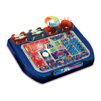
T R O N E X - Connects to the circuit
T R O N E X - Connects to the circuit
No. 32072
No. 32072
72
+
72
+
72
+
Amazing
Amazing
Science Workshop
Science Workshop
More than 72 exciting
educational experiments
™
2
1
51 52
100
3736
3938
7677
Note :
Remember to untie the string which ties the flying disc/color filter ( if available ) to the motor
before starting experiment. When the motor is rotating, do not use anything to touch the motor.
7
EXPERIMENT
Timer electric motor
Wiring Sequence
2-29-45, 30-28, 27-58, 73-57-46, 6-31, 1-77, 5-26-72-76
27
2826
2931
30
57 58
10k
7372
100uF
21
65
M
-
+
46 45
76 77
• Complete all wiring connections as indicated in the sequence. By switching ON and
pressing the push switch, the motor will rotate. At the same time, the capacitor will be
charged. When the push switch is released, the circuit is disconnected, but the motor will still keep on rotating for a while.
This is because the capacitor will discharge and release its stored electricity, thus the motor will still rotate for a while.
WARNING: Take away the color filter in this experiment. Do not connect the color filter with the motor. Otherwise
components will get overheated.
P.1 P.2 P.3 P.4