Description of product
13
AMATRON II-A DB 599 09.01
4. Fitting instructions
4.1 Console and computer
Fit basic console (14) within reach
and sight to the right hand of the op-
erator; it must be free of vibrations
and electrically conductive inside the
tractor cab. The distance from a radio
transmitter and an antenna should at
least be 1 m.
The retainer (13) is pushed on to the tube of the
console.
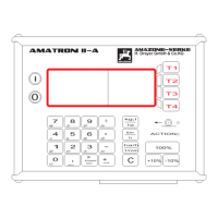
Fit the cap profile rail (10) on the retainer. Push
the computer AMATRON II-A (1) from above on
to the profile and fix using the thumb bolt.
The optimum viewing angle of the display is be-
tween 45° and 90° seen from below. Bring into the
desired position by swivelling the console.
I
Make sure that the computer housing
(1) receives via the console (10 – 14)
an electrically conductive connection
to the tractor chassis. Scratch off all
paint from the fitting surfaces.
4.2 Tractor signal distributor for
tractors without signal socket
The battery connection lead (of the computer
(17) and the sensors (18-21) are connected with
the tractor signal distributor (16). As standard
available is the Sensor X (20) (drive shaft/wheel).
Sensor Y (18) (operational position),
the speed sensor universal joint shaft
(19) and the radar (21) can easily be
retrofitted.
The tractor signal distributor (16) with its fixing
plate is bolted on to the main console or on to any
other place on the tractor.
If AMATRON II-A is exclusively used on a trailed
field sprayer the tractor signal distributor can be
dropped. The power supply is then ensured via the
switch box. The distance impulses are taken from
the wheel of the trailed field sprayer.
4.2.1 Battery connection lead
The power supply is 12 V and should be taken
directly from the battery or from the 12 V-starter.
Carefully lay the cable (17) and shorten if neces-
sary. Fit the ring tongue for the earth cable (blue)
and the wire end bushing for the + cable (brown)
with appropriate pliers. The wire end bushing for
the + cable is located in the connecting clamp of
the fuse holder.
brown = + 12 volt
blue = mass
I
The minus pole of the battery must be
connected with the chassis of the
tractor.
4.2.2 Battery connecting cable for
switch box or implement adapter
F
Fit the socket to the main console by
using the provided bolts. For the elec-
tric connection please follow discrip-
tion under 4.2.1.
 Loading...