Putting to operation
15
AMATRON II-A DB 599 09.01
4.2.4 Sensor Y (operational position)
Connect sensor Y (18) via the 3-pole bushing with the
tractor signal distributor (16). Herewith information
about the operational position is given, e.g. on soil
tillage implements by the three point hydraulics or on
the beet puller from the breaker coulter. If a switch box
or an implement adapter (e.g. field sprayer) is avail-
able, the computer receives information about the
operational position from the implement plug (4). In
this case the sensor is without any function.
Example: Tractor three point hydraulics.
Fig. 4
F
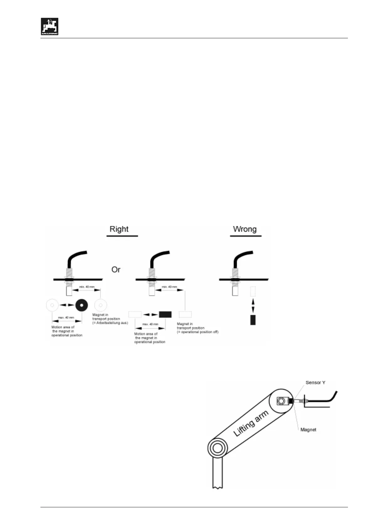
By using the provided V4A-steel bolt
the magnet is fitted to an implement
part which does not change from
transport into operational position.
The sensor is installed on an oppo-
site, fixed part of the vehicle. When in
operational position the magnet must
be in front of the sensor. The LED
"operational position" lights up on the
computer.
F
If the machine part to be monitored is
moving from the operational position by
more than 4cm from the solenoid
switch, a second magnet should be
fitted in the direction of movement of
the magnet. If the machine is in trans-
port position the magnet should have a
minimum spacing of 40 mm from the
solenoid switch..
Fig. 3

 Loading...