16
Information about the computer
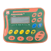
AMATRON II-A DB 599 09.01
4.3 Tractor signal distributor for
tractors with signal socket
In this case the fitting of sensors is obsolete. Insert
the plug (22) fitted to the tractor signal distributor
(16) into the signal socket of the tractor.
F
Fit the housing on the basic console
as described under 4.2.
F
Connect the battery cables as de-
scribed under 4.2.1 and 4.2.2.
The entry Y (operational position) is connected with
the plug "signal socket". An additional sensor Y
(operational position) is required when:
- the tractor electronic system does not include
the signal "operational position",
- the operational position is taken from a towed
implement.
In the latter case take care that the operational
position is not switched on via the tractor signal
socket. Interrupt the lead "operational position"
from the plug "tractor signal socket) in the tractor
distributor.
F
Assembly as described under 4.2.2.
4.4 Connection of implements
The implements mounted to the tractor or trailed
are connected via the 48-pole implement plug (3
+ 4). Via this plug the computer receives the infor-
mation from sensors, boom part switches and the
main switch. In addition the computer identifies the
implement type via an implement specific coding.
The implement relevant program and the once
entered implement data are automatically selected.
The implement plug also governs the machine.
Two connecting variations are available.
4.4.1 Connection to a machine with a
switch box
The switch box (5) is slid on to the cap profile rail,
fitted to the computer and fixed with the thumb bolt
(12).
I
Implicitely ensure that the implement
plug (3) is safely inserted in the
bushing (4).
4.4.2 Connection of implement with the
implement adapter
The implement adapter (6) is fixed on the console
(10-14) as described under 4.4.1 (switch box).

 Loading...