18
Putting to operation
AMATRON II-A DB 599 09.01
5. Putting to operation
5.1 General advice
After having installed AMATRON II-A proceed as
follows:
- Mount the implement on to the tractor, connect
the switch box or the implement adapter with
the computer being switched off.
- Switch on the computern. The implement type
is automatically identivied via the implement
plug and the relevant program with the once
entered implement data is automatically se-
lected.
- If the forward speed is faster 15 km/h and the
machine is not in operational position, the com-
puter changes to the forward speed display:
16,4 km/h
T1
T2
T3
T4
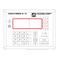
Fig. 5
5.1.1 Switching on / off the implement
By pressing key
I
switch on the AMATRON II-A
and by pressing key
O
switch off.
When switching on the display briefly shows a
choice of languages and the creation date (Fig.
6/1) in the first line and underneath the number of
version (Fig. 6/2).
14.05.00
2:52
ZAM - Streuer
Angeschaltet
Hollands
English
Deutsch
T1
T2
T3
T4
1
2
Fig. 6
I
Always ensure that the servo motors
of the fertiliser spreader set the shut-
ter slides nearly into the range of the
zero position (do not mind scales).
F
Whenever the supply voltage drops to
below 10 volts, e.g. when starting the
tractor, the computer automatically
switches off. It has to be switched on
again as described above.
After approx. 10 seconds the computer automati-
cally shows the data block order (see para. 6 / Fig.
8) on the display.
5.1.2 Description of function
T1
T2
T3
T4
ACTION
AMAZONE_WERKE
H. Dr eyer GmbH & Co .K G
0
I
-10%
+10%
100%
ha
kg;l
h
km
ha/h
1/min
C
Input
Eingabe
GH
*
OP
-
WX
9
EF
6
MN
3
UV
8
CD
5
KL
IJ
2
ST
7
AB
4
1
QR
YZ
0
=
+
:
,
(5)
(4)
(2)
(1)
(3)
(6)
(7)
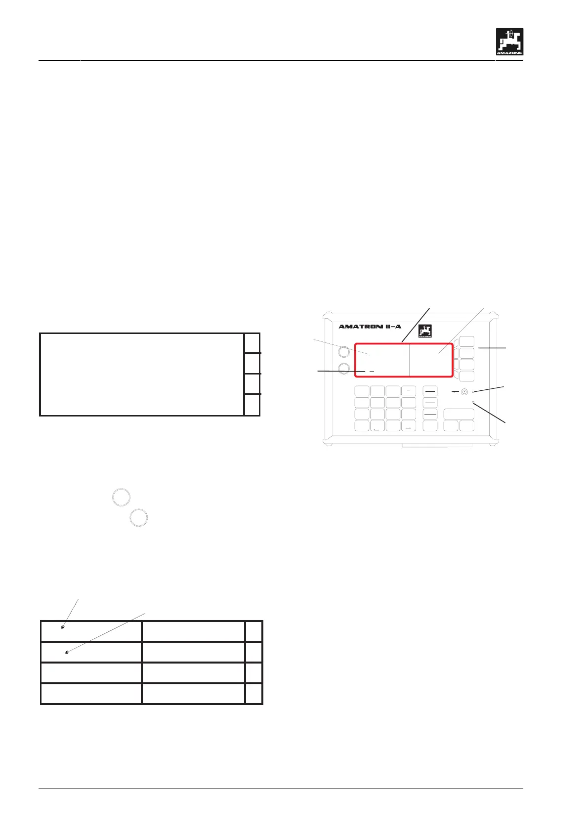
Fig. 7
(1) Alphanumerical display which can show char-
acters and figures.
(2) Softkey-keys with changing meaning which is
given by the software program via the display.
(3) Cursor.
(4)/(5) Light-emitting diode.
Display
The AMATRON II-A is provided with a 4 (lines) x
20 character alphanumerical display (Fig. 7/A). The
display is divided into two fields. The l.h. field (6)
with 4 x 12 (possible) characters is for user guid-
ance and information display.
The r.h. field (7) with 4 x 8 characters describes the
softkey-keys (Fig. 7/B). As the need arises the
function of the 4 softkey-keys can this way be var-
ied via the display.
 Loading...