42
Operating sequence field sprayer
AMATRON II-A DB 599 09.01
Tank meter:
Enter here the number of impulses / litre (Fig.
65/1), which the filling flow meter sends.
TANK-Control:
If TANK-Control is installed, enter here a "1.
• With key
T4
(Next) you will get to the next
display into which the tank filling quantity should
be entered (see para. 7.2.4).
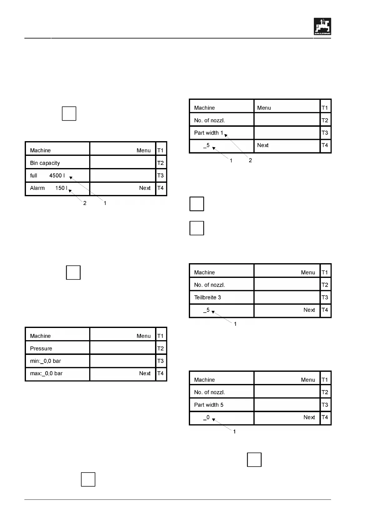
Fig. 66
Enter here the maximum tank content (Fig. 66/1).
In addition a limit value (Fig. 66/2) (e.g. 150 l) can
be entered. If this limit has been reached an visual
and audible alarm is released which indicates that
the tank is almost empty.
• Press key
T4
(go) to get to the display in
which the pressure range is determined (see
para. 7.2.5).
7.2.5 Menu "pressure range"
Fig. 67
Here the minimum and maximum allowed value of
the pressure range (in bar) is entered.
F
In order to monitor the spray pres-
sure with AMATRON II-A the pressure
range valid for the nozzles must be
entered (NOTE: observe the type of
nozzle and the advice of the nozzle
manufacturer).
• By pressing key
T4
(Next) you will get to the
display of the number of nozzles for the relevant
part section (up to 12 part sections possible)
(see para. 7.2.6).
7.2.6 Menu "number of nozzles"
Fig. 68
In this display the number of nozzles (Fig. 68/1) per
part section (Fig. 68/2) is entered. Confirm with key
=
Eingabe
Input
. The part section 1 is on the outer left hand
side seen in driving direction. By pressing key
T4
(Next) you will get to the next display in
which the number of nozzles (Fig. 69/1) for the
other part sections 2 – 12 are entered. 12 part sec-
tions in maximum can be entered.
Fig. 69
When, e.g. four part sections are available the
number (Fig. 70/1) of nozzles of the fith part sec-
tion is set to zero.
Fig. 70
• By pressing key
T4
(Next) the total amount
of nozzles (related to the entered part sections)
is shown in the next display.
 Loading...