Error Codes
This relates to a fault with the internal
temperature sensor, either through damage
or disconnection. This usually requires a
replacement thermostat to correct.
This relates to a fault with the external oor
sensor probe. Contact your electrician, who
can isolate the electricity supply and check the
sensor is connected and working correctly.
Screen Lock
In some situations where your Amber-Touch is
installed into a location where restricted access
is necessary, simply:
Press and hold the and buttons until the
appears on the screen.
To unlock, simply repeat the process until the
disappears.
ER0
ER1
3 Simple Steps to Factory Reset
1. Having initiated the advanced settings, tap the
menu button continuously until you see AFAC
2. Hold the button until “---” is displayed on
the screen
3. Press the button and switch o at the
mains to complete factory reset
Please note: the time displayed will not reset and
will stay the same prior to factory reset.
Symbol Setting Default or
1
ADJ
Temperature
calibration
N/A
Adjust measured
temperature
2
SEN
Sensor mode IN
IN: built-in sensor
OUT: oor sensor
ALL: both
sensors
(oor sensor is
the limit sensor)
3
LIT
Max oor
temperature
35°C
Adjust limitation
value,
Limitation range:
5˚C~35˚C
4
DIF
Switching
dierential
1
Adjust switching
dierential
5
LTP
Frost
protection
mode
O
Turn on/o
frost protection
function
6
PRG
Heating
schedule
5/2
2: 5/2 day mode
1: 6/1 day mode
0: 7 day mode
7
RLE
Output N/A Not Used
8
D LY
Output delay 0
Change the
delay time
9
HIT
Max
temperature
setting
50°C
Max. Limitation
temperature
setpoint (50˚C)
10
AFAC
Reset to
factory
settings
N/A
Programming
parameters
will be reset to
factory settings
when symbol
“---” appears
Advanced Settings Overview Dimensions
86mm
13mm
30mm
98mm
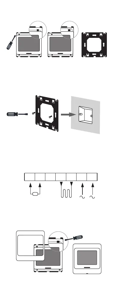
Installation Guide
STEP 1
Release the front cover by inserting screwdriver
into the hole on the underside of the front plate
STEP 2
Take the backing plate apart according to diagram
STEP 3
Install the backing plate on to the electrical
connection box with screws before any wiring
takes place
STEP 4
Ensure all wiring is undertaken by a qualied
electrician
STEP 5
Install the housing cover and lock external frame
as per diagrams
 Loading...