QSG-0123 rev 4
Copyright 2017 by American Control Electronics® - All rights reserved. No part of this document may
be reproduced or retransmied in any form without wrien permission from American Control
Electronics®. The informaon and technical data in this document are subject to change without
noce. American Control Electronics® makes no warranty of any kind with respect to this material,
including, but not limited to, the implied warranes of its merchantability and fitness for a given
purpose. American Control Electronics® assumes no responsibility for any errors that may appear in
this
document and makes no commitment to update or to keep current the informaon in this
document.
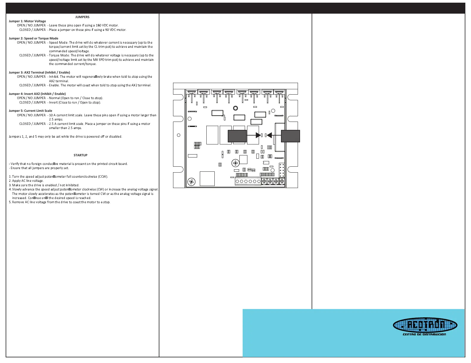
Verify that no foreign conducve material is present on the printed circuit board.
- Ensure that all jumpers are properly set.
1. Turn the speed adjust potenometer full counterclockwise (CCW).
2. Apply AC line voltage.
3. Make sure the drive is enabled / not inhibited.
4. Slowly advance the speed adjust potenometer clockwise (CW) or increase the analog voltage signal.
The motor slowly accelerates as the potenometer is turned CW or as the analog voltage signal is
increased. Connue unl the desired speed is reached.
5. Remove AC line voltage from the drive to coast the motor to a stop.
OPEN / NO JUMPER - Leave these pins open if using a 180 VDC motor.
CLOSED / JUMPER - Place a jumper on these pins if using a 90 VDC motor.
OPEN / NO JUMPER - Speed Mode: The drive will do whatever current is necessary (up to the
torque/current limit set by the CL trim pot) to achieve and maintain the
CLOSED / JUMPER - Torque Mode: The drive will do whatever voltage is necessary (up to the
speed/voltage limit set by the MX SPD trim pot) to achieve and maintain
the commanded current/torque.
Jumper 3: AX2 Terminal (Inhibit / Enable)
OPEN / NO JUMPER - Inhibit. The motor will regeneravely brake when told to stop using the
CLOSED / JUMPER - Enable. The motor will coast when told to stop using the AX2 terminal.
Jumper 4: Invert AX2 (Inhibit / Enable)
OPEN / NO JUMPER - Normal (Open to run / Close to stop).
CLOSED / JUMPER - Invert (Close to run / Open to stop).
Jumper 5: Current Limit Scale
OPEN / NO JUMPER - 10 A current limit scale. Leave these pins open if using a motor larger than
CLOSED / JUMPER - 2.5 A current limit scale. Place a jumper on these pins if using a motor
Jumpers 1, 2, and 5 may only be set while the drive is powered off or disabled.
Startup
STATUS
LED
LIMIT
LED
STATUS LED (Green)
Solid: AC line voltage is applied to the drive and the drive is enabled to run.
1 Flash: The drive is disabled or inhibited.
2 Flashes: Either Jumper 1, 2, or 5 was changed during operaon. To change these sengs, the drive
must either be disabled or powered off.
LIMIT LED (Red)
Solid: The drive is in current limit. This means the motor is asking for more current (torque) than the
drive is set to allow out. Either reduce the amount of torque required by the motor or raise the current
limit output of the drive using the Torque (CL) trim pot.
LEDs
Offset (OFFST): The OFFST seng determines the minimum motor speed when the speed adjust
potenometer or analog voltage signal is set for minimum speed. To calibrate the OFFST:
1. Set the OFFST trim pot full CCW.
2. Set the speed adjust potenometer or analog voltage signal for minimum speed.
3. Adjust OFFST trim pot unl the desired minimum speed is reached.
Maximum Speed (MX SPD): The MX SPD seng determines the maximum motor speed when the
speed adjust potenometer is set for maximum speed. To calibrate the MX SPD:
1. Set the MX SPD trim pot full CCW.
2. Set the speed adjust potenometer for maximum speed.
3. Adjust MX SPD trim pot unl the desired maximum speed is reached.
Torque (CL): The CL seng determines the maximum torque for accelerang, driving, and decelerang
the motor in both the forward and reverse direcons.
To calibrate CL:
1. With the power disconnected from the drive, connect a DC ammeter in series with the
1. armature.
2. Set the CL trim pot to minimum (full CCW).
3. Set the speed adjust potenometer to maximum forward speed (full CW).
4. Carefully lock the motor armature. Be sure that the motor is firmly mounted.
5. Apply line power. The motor should be stopped.
6. Slowly adjust the CL trim pot CW unl the armature current is 150% of motor rated
6. armature current.
7. Turn the speed adjust potenometer to minimum speed (full CCW).
8. Remove line power.
9. Remove the stall from the motor.
10. Remove the ammeter in series with the motor armature if it is no longer needed.
IR Compensaon (IR): The IR seng determines the degree to which motor speed is held constant as
the motor load changes. To calibrate the IR:
1. Set the IR trim pot full CCW.
2. Increase the speed adjust potenometer unl the motor runs at midspeed without load. A
2. handheld tachometer may be used to measure motor speed.
3. Load the motor armature to its full load armature current rang. The motor should slow down.
4. While keeping the load on the motor, rotate the IR trim pot unl the motor runs at the
4. speed measured in step 2. If the motor oscillates (overcompensaon), the IR trim pot
4. may be set too high (CW). Turn the IR trim pot CCW to stabilize the motor.
5. Unload the motor.
Calibration
Email distribuidores: acotron@acotron.com
Calz. Federalismo Sur 214, Col. Centro,
C.P. 44100, Guadalajara, Jalisco.
Tel Ocina Central: 33- 3826-7004
www.acotron.com
 Loading...