AMERICAN Flow Control
Series 2500 Resilient Wedge Gate Valve
Page 3A-11
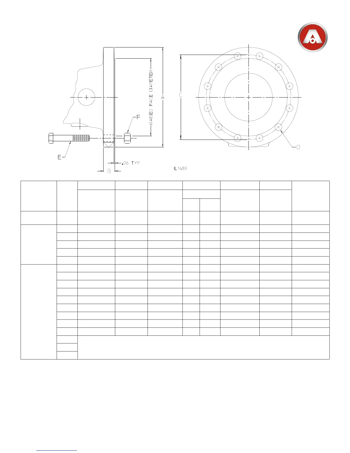
SERIES 2500 - CLASS 250 FLANGE DIMENSIONS
NOTES:
1.FlangedimensionsshownareperASMEB16.1,Class250forcastironanges.
2.Boltlengthsshownareforstandardcastironangethicknesseswiththruholes.Steelorductileiron
angeswithreducedthicknessorvalvesorttingswithtappedholesmayrequireshorterbolts.
Model
Valve
Size
A B C D E F
Raised Face
Dia.
Diameter of
Flange
Flange
Thickness
Bolt Circle
Diameter
Bolt Holes
Bolt Size
See Note 2
No. of
Hex Nuts
Required
No. Size
Series
2500
3” 8.25 1.12 6.62 8 .88 3/4-10 x 3-1/2 8 5.69
Series 2500-1
4” 10.00 1.25 7.88 8 .88 3/4-10 x 4 8 6.94
6” 12.50 1.44 10.62 12 .88 3/4-10 x 4 12 9.69
8” 15.00 1.62 13.00 12 1.00 7/8-9 x 4-1/2 12 11.94
10” 17.50 1.88 15.25 16 1.12 1”-8 x 5-1/2 16 14.06
12” 20.50 2.00 17.75 16 1.25 1-1/8-7 x 5-1/2 16 16.44
Series
2500
14” 23.00 2.12 20.25 20 1.25 1-1/8-7 x 6 20 18.94
16” 25.50 2.25 22.50 20 1.38 1-1/4-7 x 6-1/2 20 21.06
18” 28.00 2.38 24.75 24 1.38 1-1/4-7 x 6-1/2 24 23.31
20” 30.50 2.50 27.00 24 1.38 1-1/4-7 x 7 24 25.56
24” 36.00 2.75 32.00 24 1.62 1-1/2-7 x 7-1/2 24 30.31
30” 43.00 3.00 39.25 28 2.00 1-3/4 x 8-1/2 28 37.19
36” 50.00 3.38 46.00 32 2.25 2-4-1/2 x 9-1/2 32 43.69
42” 57.00 3.69 52.75 36 2.25 2-4-1/2 x 10 36 50.44
48” 65.00 4.00 60.75 40 2.25 2-4-1/2 x 11 40 58.44
54”
Not Available with Class 250 Raised Face Flanged Ends60”
66”
 Loading...