AMERICAN Flow Control
Series 2500 Resilient Wedge Gate ValvePage 3A-1
INDEX
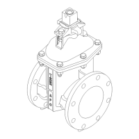
Series 2500 Ductile Iron Resilient Wedge Gate Valve
INTRODUCTION .................................................................................................................................................................................. 3A-2
FEATURES and BENEFITS ................................................................................................................................................................. 3A-3
ORDERING
Dimensions
Standard NRS (2”- 24” Sizes) .......................................................................................................................................................... 3A-4
NRS with Enclosed Miter Gearing (3”-12” Sizes) ............................................................................................................................. 3A-5
NRS with Bevel Gears (14” - 66” Sizes) ........................................................................................................................................... 3A-6
NRS with Spur Gears (14” - 66” Sizes) ............................................................................................................................................ 3A-7
OS&Y (2” - 24” Sizes) ...................................................................................................................................................................... 3A-8
Optional End Connections
Mechanical Joint, TYTON
®
/Push-On, PVC, Threaded, Flex-Ring
®
, ALPHA™................................................................................... 3A-9
Class 125 Flange ........................................................................................................................................................................... 3A-10
Class 250 Flange ........................................................................................................................................................................... 3A-11
Optional Taps on Class 125 and Class 250 Flange x Flange Bodies ............................................................................................ 3A-12
Mechanical Joint Accessories ........................................................................................................................................................ 3A-13
MaterialSpecications/PartsLists
Standard NRS:
2”..................................................................................................................................................................................................... 3A-14
2-1/2” & 3”...................................................................................................................................................................................... 3A-15
4” - 8”.............................................................................................................................................................................................. 3A-16
10” & 12”......................................................................................................................................................................................... 3A-17
4” - 8” with Alpha™Restraint Joint...................................................................................................................................................3A-18
10” & 12” with Alpha™Restraint Joint............................................................................................................................................. 3A-19
14” - 24”.......................................................................................................................................................................................... 3A-20
NRS with Enclosed Miter Gearing:
3”- 12”............................................................................................................................................................................................. 3A-21
NRS with Bevel Gears:
14” - 18”.......................................................................................................................................................................................... 3A-22
20” & 24”......................................................................................................................................................................................... 3A-23
30” - 36”.......................................................................................................................................................................................... 3A-24
42” - 54”.......................................................................................................................................................................................... 3A-25
60” & 66”......................................................................................................................................................................................... 3A-26
NRS with Spur Gears:
14” - 18”.......................................................................................................................................................................................... 3A-27
20” & 24”......................................................................................................................................................................................... 3A-28
30” - 36”.......................................................................................................................................................................................... 3A-29
42” - 54”.......................................................................................................................................................................................... 3A-30
60” & 66”......................................................................................................................................................................................... 3A-31
OS&Y:
2”.................................................................................................................................................................................................... 3A-32
2-1/2” & 3”...................................................................................................................................................................................... 3A-33
4”- 8”............................................................................................................................................................................................... 3A-34
10” & 12”......................................................................................................................................................................................... 3A-35
14”—24”.......................................................................................................................................................................................... 3A-36
Strength of Ductile Iron Valves Versus Gray Iron Valves................................................................................................................................. 3A-37
Weights........................................................................................................................................................................................................... 3A-38
Submittal Sheet ............................................................................................................................................................................................. 3A-39
INSTALLATION AND TESTING
Installation & Testing ...................................................................................................................................................................................... 3A-40
Class 125 Flanged Valve Installation (Applies to 4” thru 12” sizes only) ........................................................................................................ 3A-41
ALPHA™ Restraint Joint Installation (Applies to 4” thru 12” sizes only) ........ .................................................................................... 3A-42,3A-43
OPERATION AND MAINTENANCE
Operation, Maintenance, Spare Parts ............................................................................................................................................................ 3A-44
Troubleshooting Guide ................................................................................................................................................................................... 3A-45
REPAIRS
NRS:
2”, 2-1/2” & 3” ......................................................................................................................................................... 3A-46, 3A-47, 3A-48
4”- 8” ................................................................................................................................................................................. 3A-49, 3A-50
10” & 12” ............................................................................................................................................................................. 3A-51, 3A-52
NRS with Enclosed Miter Gearing ...................................................................................................................................... 3A-53, 3A-54
OS&Y:
2”......................................................................................................................................................................................... 3A-55, 3A-56
2-1/2” & 3”.......................................................................................................................................................................... 3A-57, 3A-58
4”—8” ................................................................................................................................................................................. 3A-59, 3A-60
10”—24”.............................................................................................................................................................................. 3A-61, 3A-62
SPECIFICATIONS................................................................................................................................................................................ 3A-63

 Loading...