This document describes the American Flyer FasTrack Remote Switch, an S-Gauge track accessory designed for model train layouts. The switch allows users to control train routes, enabling complex track configurations such as joining track loops, creating switching yards, or adding sidings. It offers both conventional and Command Control operation, providing flexibility for various model railroading setups.
Function Description
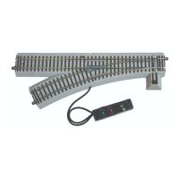
The American Flyer FasTrack Remote Switch serves to divert trains from one track path to another. It integrates seamlessly with other American Flyer FasTrack track sections, ensuring secure connections and good electrical contact through interlocking roadbed sections and metal rail joiners. The switch mechanism includes "points" or moving rails that physically change the track path. An illuminated switch lamp on the roadbed indicates the current path, with different colors (red for curved, green for straight) designating the switch's position.
The switch can be operated in two primary modes: conventional and Command Control. In conventional mode, the switch is controlled either by a manual lever on the attached controller or by rotating the switch lamp itself. For Command Control operation, the switch is programmable and responds to commands from a CAB remote (such as CAB-1, CAB 1-L, or LEGACY remote). This allows for wireless control and integration into more advanced, automated layouts.
A key feature of the Command Control functionality is "Soft Set Technology," which enables programming the switch's ID number (1-99) without needing to physically access a program button on the switch itself. This is particularly useful for switches that are difficult to reach once installed on a layout. Each switch can be assigned a unique ID, preventing interference when multiple Command Control switches are present.
The switch also supports train route information. In TMCC1 operation, Routes 1-9 are supported and stored directly in the switch, assigned by the Cab-1 controller. These routes define a sequence of switch positions ("through" or "out") and are activated with a randomized time delay (up to 2 seconds) to prevent excessive load on the track power transformer when multiple switches are activated simultaneously. For LEGACY operation, Routes 1-99 are supported and stored in the LEGACY base, with route assignments managed through the LEGACY manual's route builder.
The switch requires 14 Volts AC to operate. It can be powered directly from the track or through a separate power supply. Powering via a separate supply is beneficial when track power is off or set to a low voltage, especially in conventional environments, ensuring consistent operation of the switch mechanism.
Usage Features
- Easy Track Connection: FasTrack sections connect easily with interlocking roadbed and metal rail joiners, ensuring secure and reliable electrical contact. Users simply line up track sections, insert rails into joiners, and press the roadbed sections together until they snap into place. Wires should be fed through a notch in the roadbed during connection.
- Conventional Operation:
- Controller Lever: The switch can be operated by pulling a lever on the attached controller. The lights inside the controller change color (red for curved, green for straight) to indicate the switch's position. Track power must be on for controller operation.
- Switch Lamp Rotation: Alternatively, users can rotate the switch lamp on the roadbed to change the switch position. The colored lenses on the lamp indicate the new path. If the lamp detaches, it can be re-inserted into its slot.
- Command Control Operation:
- Programming: To use Command Control, set power supplies to full (up to 18 volts AC). Press the program button on the switch (or use Soft Set Technology), then use a CAB remote to assign a switch ID number (1-99). The switch's LED will flash during programming and stop when addressed.
- Remote Commands: Once programmed, the switch responds to AUX1 (straight through) and AUX2 (curve) commands from the CAB remote. The controller's LEDs will change color to reflect the switch's throw route.
- Switch Stand Location Adjustment: The switch stand, which houses the control mechanism, can be repositioned to either the inside or outside of a track loop. This involves removing screws, carefully detaching roadbed sections, and re-installing the switch stand in the desired location, ensuring the pin on the mechanism is inserted into the control arm's slot.
- Controller Cable Routing: The controller cable is initially routed through a notch on the curved side of the roadbed. Users can reroute it to the straight side by gently lifting the cable, bending metal tabs, moving the cable, and then bending the tabs back down to secure it.
- Wireless Operation: For wireless Command Control operation, the manual controller cable can be removed. This involves loosening terminal screws, pulling out the wires, and then replacing the screws to prevent misplacement. The detached controller should be stored safely if future conventional use is desired.
- Separate Power Supply Option: The switch can be powered independently of the track. This requires removing a jumper between the TRACK POWER and SWITCH POWER terminals, then connecting a separate power supply's Power/A terminal to the SWITCH POWER terminal and its Common/Ground/U terminal to the POWER COM terminal on the switch. The black wire from the controller should remain attached to the Power Com terminal. This ensures the switch operates even when track power is low or off.
Maintenance Features
- LED Illumination: The switch lamp and switch controller are illuminated by light-emitting diodes (LEDs). These LEDs are designed for the life of the switch and are not user-serviceable. If an LED needs replacement, users should contact Lionel Service.
- Warranty Information: The product comes with a one-year limited warranty from the original date of purchase against defects in materials or workmanship, provided it was purchased through a Lionel Authorized Retailer. The warranty does not cover normal wear and tear, light bulbs/LEDs (as they are not user-serviceable), commercial use defects, or damage from abuse/misuse. The warranty is non-transferable and voided by product modification.
- Obtaining Service: For service, users should bring the item, along with a dated sales receipt and completed warranty information, to the nearest Lionel Authorized Service Station. Alternatively, users can contact Lionel Customer Service directly to obtain a Return Authorization (RA) number before shipping the product. Products must be packed in original packaging and shipped prepaid and insured. Products requiring service without a receipt from an Authorized Retailer may incur charges for parts, but not labor, if within a certain timeframe from manufacture and purchase.