Ameritron RCS-10 Instruction Manual
3
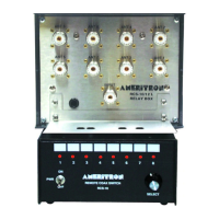
Control Box Features
Battery or Line Operated: Operates from any filtered 12-16 Vdc supply capable of
supplying 500mA continuous.
Easy-to-Read Antenna Indicators: Eight wide-spaced LED’s indicate the selected
antenna.
Wide Profile: 6-1/4” W x 4-5/8” D x 3-1/4 H helps prevent unwanted movement when
turning selector switch.
Flexible Interface: Accepts and outputs one-of-eight control signals, and outputs three-
line BCD data.
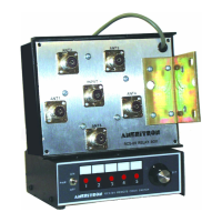
REMOTE RELAY UNIT
Typical Electrical Characteristics
Maximum Loss:
30MHz (and lower) negligible, 60MHz under 0.1dB, 150MHz under .25dB
15 MHz 30MHz 60MHz 150MHz
Worse Ports Negligible Negligible Under 0.1dB Under 0.25 dB
Maximum 50-ohm VSWR:
Below 30MHz under 1.25:1, below 60MHz under 1.3:1, below 150Mhz under 1.8:1
15 MHz 30MHz 60MHz 150MHz
Worse Ports Negligible Under 1.25:1 Under 1.3:1 Under 1.8:1
60dB Port-toport Isolation at 150MHz (unused port terminated into 50 ohms) in –dB.
Isolation improves greatly at lower frequencies.
150 MHz Port-to-port crosstalk:
Worse case –19dB, typical –30dB, best case –60dB Port-to-port Isolation at 150 MHz
(unused port terminated into 50 ohms) in -dB. Isolation improves greatly at lower
frequencies.
 Loading...