EasyManua.ls Logo

AMERITRON SDC-103 - User Manual

AMERITRON SDC-103
13 pages
Print Icon
To Next Page IconTo Next Page
Loading...
AMERITRON SDC-103
INSTRUCTION MANUAL
116 Willow Road
Starkville, MS 39759 USA
662-323-8211
Version 0A
Printed in U.S.A.
Automatic Screwdriver Antenna
Controller for ICOM Radios
PLEASE READ THIS MANUAL BEFORE OPERATING THIS EQUIPMENT !
Question and Answer IconNeed help?

Do you have a question about the AMERITRON SDC-103 and is the answer not in the manual?

Overview

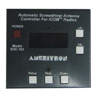
The AMERITRON SDC-103 is an Automatic Screwdriver Antenna Controller designed for use with ICOM radios. This instruction manual provides comprehensive details on its installation, features, and operation.

Function Description:

The SDC-103 automatically adjusts the resonant frequency of a screwdriver antenna by reading CI-V frequency data from a compatible ICOM radio. It then adjusts the antenna's resonant frequency accordingly. The controller supports both single and dual sensor antenna setups, requiring an antenna sensor for proper counter and automatic operation. It also allows for storing three pre-selected antenna positions.

Important Technical Specifications:

  • Power Supply: Operates from a 12V vehicle supply.
  • Fuse Requirement: A 5 Amp slow-blow fuse is typically recommended for the red +12VDC wire, depending on the antenna motor's current draw.
  • Wire Gauge: 16 AWG wire is recommended for extending red (+12VDC) and black (Vehicle Ground) wires. Motor control wires should be no smaller than 18 AWG, and sensor wires no smaller than 24 AWG.
  • Motor Operating Voltage: Designed for 12-volt screwdriver antennas. For antennas operating on 3 or 4 volts, a dropping resistor (e.g., 5 Ω/10 Watts) must be used inline with one of the motor control lines to prevent damage.
  • Maximum Input Voltage: Do not apply voltages greater than 18 volts to the unit, as this can cause permanent damage.
  • CI-V Settings (ICOM Radio):
    • CIV Baud: AT(AUTO)
    • CIV ADD: 5E
    • CIV TRN: ON
    • CIV 731: OFF
  • Trip Current: Default setting is C075 (0.75 amps), suitable for the Ameritron SDA-100 Screwdriver Antenna. This value is programmable and protects the motor from stalling damage.
  • Relay Delay: Programmable from 0ms to 200ms, with a default of 20ms. This controls the duration the relays are reversed when the motor stops.

Usage Features:

  • Automatic Antenna Tuning: Tunes the antenna automatically when connected to an ICOM radio.
  • Programmable Presets: Stores 3 programmable antenna positions.
  • Manual Control: Dedicated UP/DN buttons for manual antenna adjustment.
  • Motor Protection: Features a current sensor trip to protect the antenna motor from overcurrent due to stalling.
  • Auto-Park: Lowers the antenna to its lowest position and zeros the counter. Activated by simultaneously depressing the Up and Down buttons for 2 seconds.
  • Power Button: Push-button switch to power the controller on and off.
  • Setup Button: Accesses the setup menu for adjusting trip current, relay delay, and UP features.
  • Skip Button: Used in the band menu to choose which bands are active for automatic antenna control.
  • Enter Button: Used to save selected values and navigate through menu settings.
  • Reset Function: Clears all memory positions by holding the Down button while powering up.
  • Band Menu Navigation: Allows activation/deactivation of frequency bands (160m, 80m, 40m, 30m, 20m, 17m, 15m, 12m, 10m, 6m).
  • Frequency Menu Navigation: Programs upper and lower frequency limits for each active band. The controller uses these limits to adjust the operating frequency. This involves:
    1. Holding the Enter button while powering on to move the antenna to its lowest position.
    2. Tuning the radio's VFO to the highest operating frequency of the displayed band and adjusting the antenna with UP/DN buttons until tuned.
    3. Pressing Enter to save the position.
    4. Setting the radio to the lowest frequency of the band and tuning the antenna for resonance.
    5. Pressing Enter to store the position and continue to the next band.
    6. Repeating this process for all active bands.
  • Saving Memory Positions: Three antenna positions can be saved by using the UP/DN buttons to tune the antenna, then pressing and holding Select, Skip, or Enter until "done" is displayed.
  • Operation with ICOM Radio:
    1. Power on the ICOM radio.
    2. Power on the SDC-103 (should display "Con").
    3. Tune the frequency dial on the ICOM radio; the antenna should move according to settings.
    4. Apply low power (5-10 watts) and verify SWR with a meter. Small adjustments can be made with the UP/DN buttons.

Maintenance Features:

  • Troubleshooting: The manual advises checking the appropriate sections for solutions to problems.
  • Technical Assistance: Contact information for MFJ Technical Service (phone, FAX, email) is provided for issues not resolved by the manual. Users are advised to have their unit, manual, and station information ready.
  • Installation Warnings:
    • Do not reverse the polarity of the Red and Black wires to avoid damage.
    • An RF choke must be placed around the control lines at the antenna and on the data cable to prevent damage from RF.
    • Ensure proper motor operating voltage by using a dropping resistor if necessary for lower voltage antennas. Failure to do so will damage the motor.

AMERITRON SDC-103 Specifications

General IconGeneral
BrandAMERITRON
ModelSDC-103
CategoryController
LanguageEnglish