Do you have a question about the Amersham AKTA UPC-900 and is the answer not in the manual?
Overview of the UPC-900 monitor's features and capabilities.
Essential safety precautions and warnings for operating the monitor.
Instructions for unpacking the module and checking contents.
Guidelines for module placement and environmental conditions.
Step-by-step guide for installing the optical unit, flow cell, and lamp assembly.
Procedure for connecting and installing the conductivity flow cell.
Steps for mounting the pH flow cell holder and inserting the pH electrode.
Details on connecting signal cables for chart recorders and other devices.
Instructions for establishing a communication link with a PC or system.
Critical information on safely connecting the module to mains power.
Pre-operation checks and initial setup steps, including calibration.
Guide for installing optional filters to change measurement wavelengths.
Procedure for switching the module on/off and the self-test process.
How to navigate menus and adjust settings using the dial and buttons.
Explanation of the different main operating menus and their functions.
Instructions for manually switching the UV lamp on/off.
How to display and interpret UV absorbance readings.
Procedure for setting the UV signal baseline to zero before measurements.
Method for setting eventmarks on the UV curve.
How to configure analogue output signals for measurements.
Steps for calibrating the conductivity measurement for accuracy.
Detailed procedures for calibrating the pH electrode.
Using the moving average filter to reduce noise in UV signals.
Guidance on replacing the UV flow cell.
How to display and interpret pH, temperature, and conductivity readings.
Procedures for storing the module and shutting down the system.
How the module behaves and restarts after a power interruption.
Schedule and overview of routine maintenance tasks for the monitor.
Instructions for cleaning the module housing and checking lamps.
Method for cleaning the UV flow cell without removing it.
Procedure for cleaning the UV flow cell after removal.
Steps for cleaning the conductivity flow cell while installed.
Procedure for cleaning the conductivity flow cell after removal.
Guidance on replacing the conductivity flow cell.
Methods for cleaning the pH electrode to restore performance.
Steps for replacing the pH electrode.
General advice and information for contacting support.
Identifies common faults and provides suggested actions for resolution.
Lists error messages, their meanings, and recommended actions.
General description of the UPC-900 monitor and its measurement capabilities.
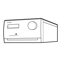
Detailed overview of the UPC-900 monitor unit, connectors, and functions.
Explanation of the components and operation of the UV optical unit.
Description of the pH electrode's construction and compatibility.
Details on the conductivity cell's design, operation, and temperature sensing.
Procedures for checking internal values, lamp status, and recorder functions.
Overview of setup menus for adjusting module parameters.
How to enable or disable the display of temperature in main menus.
Setting up temperature compensation for conductivity measurements.
Configuring the reference temperature for conductivity compensation.
Procedure for adjusting the conductivity cell constant.
Steps to set the cell constant for the conductivity flow cell.
How to enable or disable the display of conductivity in main menus.
Configuring temperature compensation for pH measurements.
How to enable or disable the display of pH in main menus.
Adjusting the averaging filter constant to reduce UV signal noise.
Resetting the UV lamp run time counter after replacement.
How to enable or disable UV absorbance display in main menus.
Changing the display language of the monitor.
Setting the unique number for the monitor on the UniNet-bus.
Adjusting the display angle for better viewing height.
Configuration and usage of alarm and count-down timers.
Accessing service-related displays and information.
Detailed overview of the monitor's menu structure and navigation.
Detailed technical specifications for the monitor's functions and components.
Specific operating parameters and performance data for measurements.
Information on the monitor's physical characteristics, connectivity, and materials.
| Brand | Amersham |
|---|---|
| Model | AKTA UPC-900 |
| Category | Measuring Instruments |
| Language | English |