AMETEK CTS AMP 200N series
Manual for Operation V 4.0.3 12 / 60
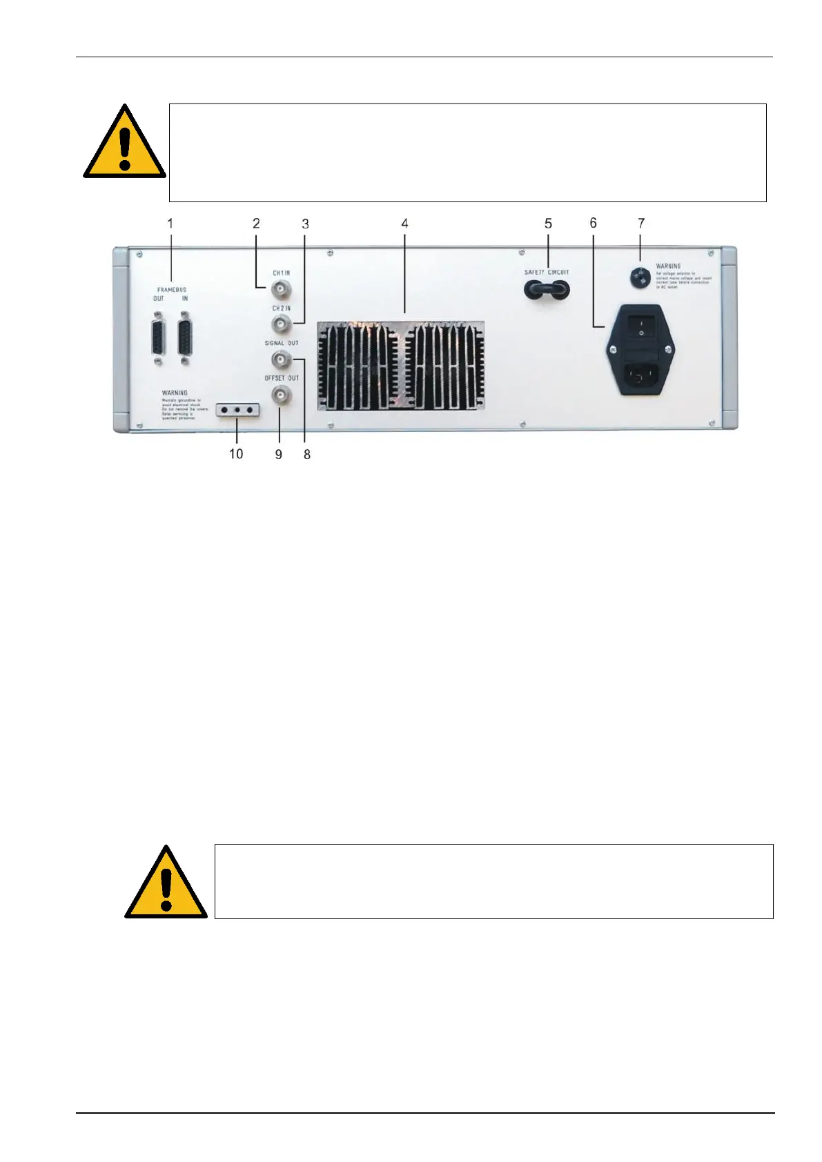
4.2 Rear view
Attention: For cooling the AMP200N a minimum free space at the rear of 20cm is requested
1 Framebus
2 CH 1 IN
3 CH 2 IN
4 Ventilation
5 Safety Circuit
6 Power on switch with fuse
7 Mains selector 115V / 230V
8 Signal OUT
9 Offset OUT
10 Reference Earth connection
1 Frame Bus
Daisy Chain bus with Sub D 15 poles male and female connectors. This port is used as communication and
control bus between EM Test devices. A framebus terminating network is mandatory when the AMP 200Nx
is at the end of the daisy chain.
2 CH 1 IN
BNC input -10V to +10V: This input is used for controlling the VDS 200 or internal amplifier. In switch off
Status the connection is passing to the Signal out output.
3 CH 2 IN
BNC input -10V to +10V to internal amplifier.
4 Ventilation
The cooling output needs at least 20cm space for a free airflow.
5 Safety Circuit
The Safety Circuit is a 12V loop who switches off the power supply of the amplifier. The ac voltage will be
interrupted by a relays.
Attention: After open the Safety circuit there is still same energy in the storage capacitors
of the amplifier.
6 Power on switch with mains fuse
The switch is part of the mains filter. Mains fuses are part of the filter. (230V / 3.15AT and 115V / 6AT).
After switch on the power LED is flashing few seconds, till the AMP200 is ready for use.
7 Mains selector
Selection of 115V / 230V
8 Signal OUT
Control output to system dc source (normally VDS200N). The control signal is generated in the AutoWave or
AMP 200 internal and pass through the AMP200N to the “analog IN” of the VDS200N.
9 Offset OUT
Output control signal from the AMP 200N internal DC source (-10V to +10V).

 Loading...