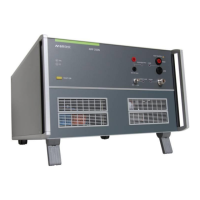
AMETEK CTS AMP 200N series
Manual for Operation V 4.0.3 19 / 60
6 Operation
The AMP 200N needs an AutoWave generator or a Netwave for operate. The AutoWave/Netwave generator
controls the AMP 200N via the framebus. The user needs the autowave.control or Netwave.controlsoftware
for operate the system with the AMP200N.
6.1 Test Setup with Autowave
The typical test setup with the control cable connections is illustrate in figure 4.1
For operation with AMP200N the software
AutoWave.control is necessary. For device control the
following interfaces must be used:
Devices GPIB Ethernet
AutoWave AMP200N X X
AutoWave AMP200N VDS200x X
NOTE: If the user has a device which needs GPIB,
(example VDS200x), it is mandatory to use
the GPIB interface.
Figure 8 General Test setup with AMP 200N and AutoWave
6.1.1 Cabeling with Autowave
The general cabling with AMP 200N is
illustrated in Figure 3.2.
There are many applications that use an
AMP200N. Please refer to the setup
description in the specific standards.
Chapter Applications shows a selection test
setup and their specific software settings for
different tests.
List of cable connections:
Computer to…
AutoWave GPIB / IEEE488
Ethernet
AutoWave & VDS200x GPIB / IEEE488
AutoWave to AMP 200N
Framebus OUT Framebus IN Sub-D 15 poles
CH 1 CH 1 IN BNC
CH 2 CH 2 IN BNC
AMP 200N to VDS 200x
Signal OUT 0-10V BNC
AMP 200N
Framebus OUT Termination Sub-D 15 poles
Figure 9 System cabling using AMP 200N
6.2 Test Setup and cabeling with Netwave and AMP200N Series
The typical test setup with the control cable connections is illustrate in figure 4.3

 Loading...