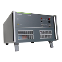
AMETEK CTS AMP 200N series
Manual for Operation V 4.0.3 50 / 60
12.6 Immunity to GLoyd GL VI-7-2 – 20 (DC)
11.6.1. DC power supply
For loading this testfile the user has to open the file “GL VI-7-2 – 20 (DC).wim”.
1. Press in the main Window “Immunity play” .
2. Load the file “GL VI-7-2 – 20 (DC).wim”. The program will open the test
Default test setup continuous interference
The software will show the picture of SAE J1113-2 with a very similar test setup.
Figure 28 Setup for GL VI-7-2 – 20
Remark : The optional Shunt Capacitor is not part of the GLoyd test setup. In accordance with other standards
with similar test as in SAE J1113-2, MIL STD 461 CS 101 or RTCA DO-160D Section 18, it may be
necessary to use a shunt capacitor. The shunt capacitor is for shunt the dc source terminals for the
RF signal, if difficulty is encountered in obtaining sufficient test voltage.
GLoyd GL 2003 VI-Teil 7 Kapitel 2 Test Parameter requirements
Figure 29 Signal voltage level for DC supply

 Loading...