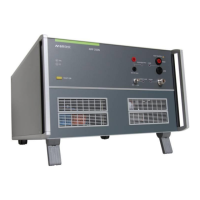
AMETEK CTS AMP 200N series
Manual for Operation V 4.0.3 52 / 60
12.7 Ripple immunity with voltage and current measurement
0.5 R
Computer
AMP200Nx
CN 200N1
EUT
NetWave
DC
Fm100
AC
Fm8
C-Box 100
+
_
Framebus
Signal Out
Source In
Framebus
Signal Out
DVP
+
-
Current
Probe
Power
Supply
4mm
to
BNC
BNC
to
4mm
Verification
Load
Power
Supply
Figure 30 Setup for ripple immunity with swapped voltage and current measurement channels
The above figure shows the setup for a closed-loop ripple immunity testing. The AMP 200N measurement
channels are used to measure the ripple current and voltage at the EUT terminals.
AMP 200N measuring input maximum allowed input voltages:
Voltage Measuring Input: max. 200 Vpp
Current Measuring Input: max. 10 Vpp
Differential voltage probe
EM Test PVS 7 or Teseq MD 210
Keysight N2780B (2MHz, 500A), N2781B (10 MHz, 150A) or N2782B (50MHz,
30A) with external power supply
EM Test C-Box 10/100-1000
EM Test SVP CL 100 (100 Ohms)
Hints for the setup:
- Use active voltage and current probes (to match the impedance of the AMP measuring channels).
Passive probes are not suitable.
- Power the differential voltage probe with batteries. Using an external power supply may generate
interference that disturbs the ripple test.
- AMP measurement channels can be swaped in case higher voltage measurement resolution is required.
In this case additional adapters from BNC to 4mm lab connectors (or vice versa).
- It is recommended to first verify the setup and performance using a verification load instead of the EUT.

 Loading...