Version 15-02-2023 BG 65 dMove / BG 66 dMove Page/Seite 39 / 54
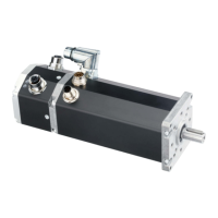
Anschluss über 12+3-poligen Stecker für Motor
Bei dieser Pinbelegung handelt es sich
um die Standard-Belegung. Führend ist
die auf der Motorzeichnung angegebe-
ne Pinbelegung.
Beim Wechsel von BG 65S auf
BG 65/66 dMove ist die Pinbelegung
zu beachten. Diese Motoren sind nicht
kompatibel.
Connection via 12+3-pin connector for motor
This pin assignment is the standard pin
assignment. Leading is the pin assi-
gnment shown in the motor drawing.
When changing from BG 65S to BG
65/66 dMove, the pin assignment must
be observed. These motors are not
compatible.
Plug pin/
Stecker Pin
Signal (IO)
Signal (IO)
Signal (CO)
Signal (CO)
Lead colour of the connection cable with 12+3-pin
connector
(1)
/
Litzenfarbe der Anschlussleitung mit 12+3-poligem
Stecker
(1)
A U
Power
U
Power
blue/ blau
1.38mm
2
B GND GND black/ schwarz
C N. C. N. C. brown/ braun
1 IN0 IN0 yellow/ gelb
0.14mm
2
2 IN1 IN1 blue/ blau
3 IN2 IN2 brown/ braun
4 IN3 IN3 green/ grün
5 OUT1 OUT1 grey/ grau
6 OUT2 OUT2 grey pink/ grau pink
7 AI+ AI+ pink/ rosa
8 AI- AI- violet/ violett
9 U
Log
U
Log
red/ rot
10 N. C. N. C. black/ schwarz
11 CAN High
(2)
N. C. red blue/ rot blau
12 CAN LOW
(2)
N. C. white/ weiß
(1)
With standard connector./
Mit Standard-Stecker.
(2)
Only versions without seperate CAN connectors/
Nur bei Versionen ohne seperate CAN Stecker
 Loading...