30
BG 75 EC www.dunkermotoren.de Version 06.2019
6.2.10 Prinzipschaltbild Spannungsversorgung
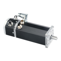
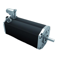
BG75 EC
Beim Einschalten einer Vielzahl von Antrieben muß
der Einschaltstrom über eine Softstartfunktion rea-
lisiert werden. Das kann entweder durch entspre-
chende Wahl eines Netzteiles oder wie im nachfol-
genden Prinzipschaltbild erfolgen.
Der grau hinterlegte Ausschnitt des Prinzipschaltbildes
zeigt den Anschluss eines BG75 EC. Es können auch
mehrere BG-Motoren, wie dargestellt, hintereinander
geschaltet werden.
1) Der anschließende, nicht grau hinterlegte Be-
reich des Schaltbildes, stellt nur sinnbildlich mehrere
Motoren und deren Anschluss dar. Wenn mehrere BG-
Motoren in dieser Art kombiniert werden, müssen die
Prinzipschaltbilder für die Spannungsversorgung der
entsprechenden Motorvarianten (BG 45, 65, BG75)
in den jeweiligen Bedienungsanleitungen beachtet
werden.
Stromspitzen beim Einschalten
mehrerer hintereinander geschalteter
Motoren!
Die Folge:
Die integrierte Elektronik kann zerstört
werden.
► Softstartwiderstand verwenden
(Siehe Prinzipschaltbild)
VORSICHT
Motor
BG75 EC
Motor (n)
Motor (n+1)
1A Träge
8A Träge
Bremsschaltung
1A time lag fuse/ Träge
25A time lag fuse/ Träge
Soft start resistor/
Softstartwiderstand
2,2/ 50W
GND
Logic Supply 24V DC
Power Supply
(Nominal Voltage)
GND
min. 1000F/Amp.
min. 2,2/
min. 50 W
6.2.10 Schematic circuit power supply
BG75 EC
The inrush current must be realized by a soft start
function when a variety of motors will be switched on.
This is either possible by using of a adequate power
supply unit or as shown in the schematic circuit.
The grey section of the schematic circuit shows the
precisely connection of a BG75 PB. It is also possible
to connect in series more BG-motors as shown.
1) The non-grey section of the schematic circuit shows
only emblematical the connection of several motors.
When a number of BG-motors will combined in this
way, it is neccessary to attend the schematic circuit in
the user manual about the corresponding motors
(BG 45, BG65, BG75).
Peak current by switching-on of a
variety of series-connected
motors!
Consequence:
Destroying of the integrated electronics
possible.
► Using a soft start resistor
(See Schematic circuit)
CAUTION
 Loading...